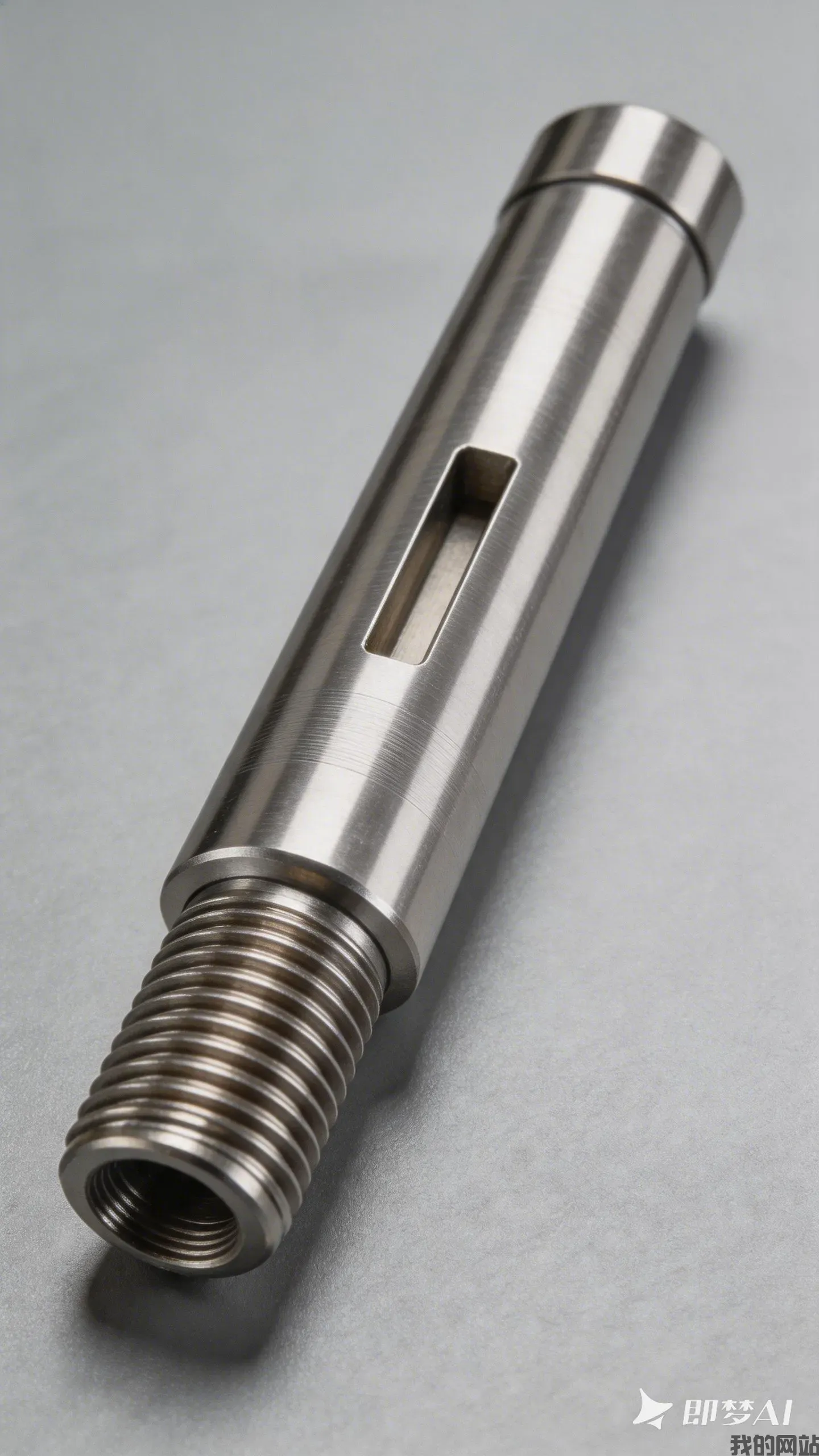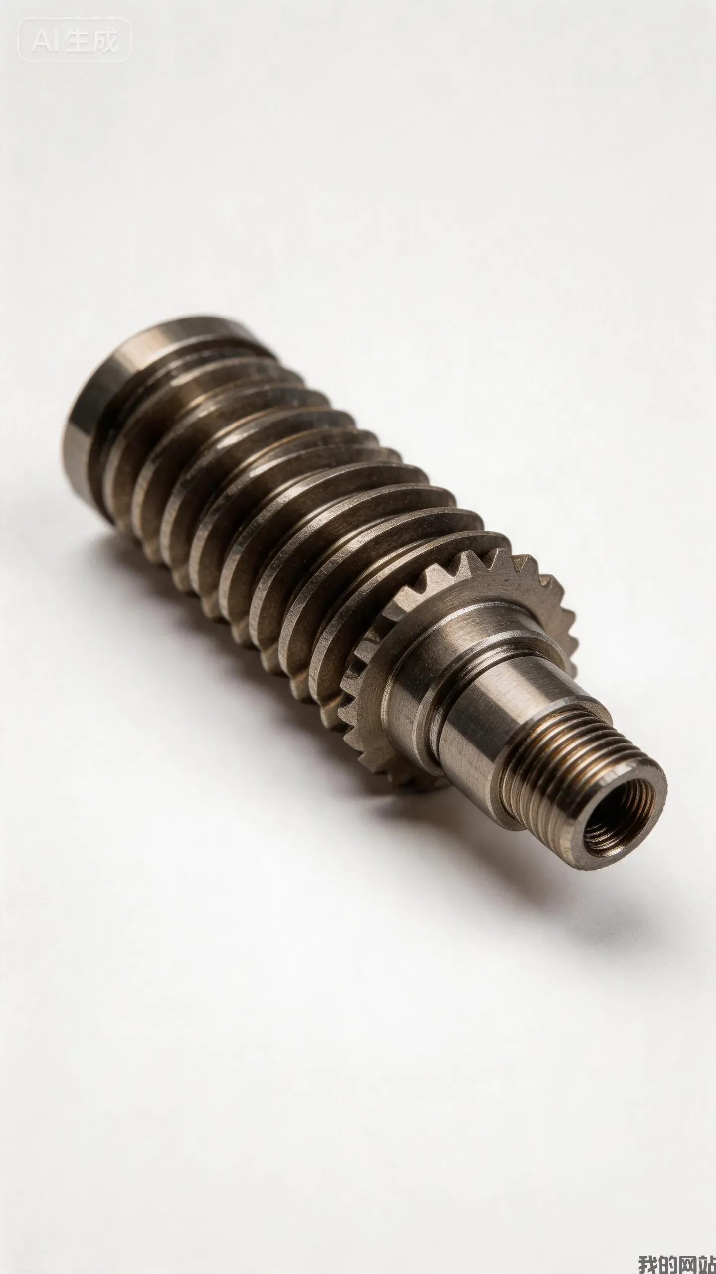
5G Infrastructure Manufacturing in 2025: Precision Components for Volume Scaling
The transition from 5G pilot networks to nationwide commercial deployment has created an unprecedented demand for precision-manufactured components. For 2025, the answer to scaling 5G infrastructure is not merely adding more production lines; it is achieving micrometer-level tolerances at mass-production volumes, specifically maintaining ±0.005 mm on antenna arrays and ±0.01 mm on waveguide flanges while ramping from thousands to millions of units annually. This requires a fundamental shift in CNC machining strategy, material selection, and quality assurance protocols.
The Volume Challenge: From Prototypes to Millions of Units
The 5G rollout is fundamentally different from 4G. While 4G macro cells required roughly 3-5 antennas per site, a typical 5G Massive MIMO (Multiple Input Multiple Output) base station uses 64 to 256 individual antenna elements. According to industry data, a single 5G macro site can require over 1,200 precision metal parts. When scaling to cover a country with 500,000 sites, that translates to 600 million components.
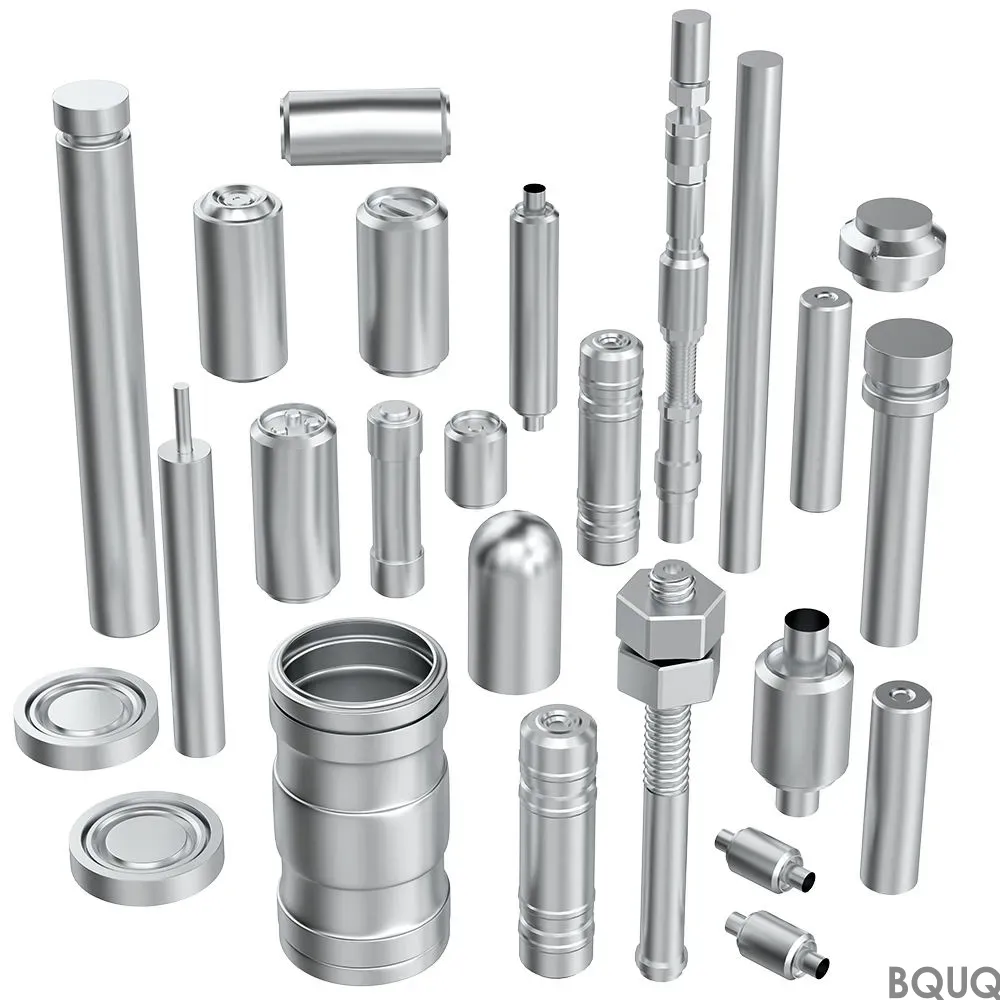
This volume forces manufacturers to abandon traditional low-rate initial production (LRIP) methods. The new benchmark is "first article correct" at scale. At BQUQ, we achieve this through multi-axis CNC machining centers running 24/7 with automated tool wear compensation. For instance, our machining centers maintain a positional accuracy of ±0.003 mm on aluminum alloy 6061-T6 housings for remote radio units (RRUs), which is critical because a deviation of 0.01 mm in the mounting surface can cause passive intermodulation (PIM) values to exceed the -150 dBc threshold required by major carriers.
Material Selection for Thermal and RF Performance
Volume scaling fails if materials cannot handle the thermal load. 5G power amplifiers generate up to 300% more heat per square centimeter than 4G equivalents. The industry standard is shifting toward high-conductivity copper alloys and aluminum-silicon carbide (AlSiC) composites for heat sinks and baseplates.
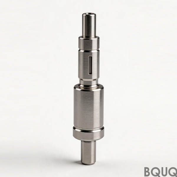
For RF components, the material choice impacts signal integrity directly. We recommend the following specifications:
| Component | Material | Thermal Conductivity (W/m·K) | Coefficient of Thermal Expansion (ppm/°C) | Typical Tolerance | ----------- | ---------- | ------------------------------- | ------------------------------------------ | ------------------- | RRU Heat Sink | Al 6061-T6 | 167 | 23.6 | ±0.05 mm flatness | Waveguide Flange | C101 Copper | 391 | 17.0 | ±0.01 mm planarity | Antenna Reflector | Al 5052-H32 | 138 | 23.8 | ±0.02 mm profile | Cavity Filter | Silver-plated Brass | 121 | 19.0 | ±0.005 mm bore | mmWave Patch Antenna | Rogers 4350B + Cu | 0.7 (laminate) | 14-17 | ±0.03 mm etch |
|---|
These selections ensure that the passive intermodulation (PIM) performance remains stable from -40°C to +85°C operating range. For volume production, we use single-hit machining strategies—meaning one machine does the complete 3D contouring without re-fixturing—which reduces setup errors by 90% compared to traditional 3-op processes.
CNC Machining Strategies for High-Volume RF Components
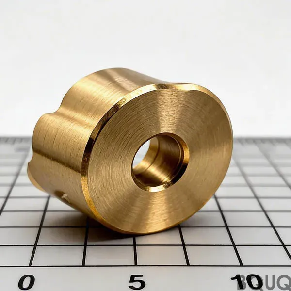
The bottleneck in 5G scaling is not the semiconductor; it is the metal cavity filters and connectors. A 64-element antenna array requires 64 individual phase-shifter housings, each with an internal cavity that must hold a tolerance of ±0.008 mm on the critical dimension (CD) to maintain the ±2.5-degree phase error budget.
To scale this, we employ a "lights-out" manufacturing approach with in-process probing. Our palletized systems allow for 120-hour unmanned operation. The key parameters include:
- **Spindle speed:** 20,000 RPM for aluminum finishing, 8,000 RPM for copper - **Feed rate:** 2,500 mm/min for roughing, 800 mm/min for finishing passes - **Tool diameter:** 0.8 mm ball-nose end mills for internal corner radii - **Surface finish:** Ra 0.4 micrometers on RF sealing surfaces
A critical innovation is using vibration-damped boring bars for the through-holes in waveguide flanges. This reduces chatter marks, which would otherwise create micro-cracks that degrade PIM under thermal cycling. In 2025, we are seeing a 30% cost reduction per unit by switching from EDM to high-speed CNC milling for these features, provided the batch size exceeds 5,000 pieces.
Cost Per Part and Lead Time Economics
Volume scaling requires a clear cost model. Here is a comparison of typical costs for a 2.4 GHz cavity filter body (size 150mm x 80mm x 40mm) at different volume thresholds:
| Quantity (pcs) | Unit Price (USD) | Lead Time (days) | Setup Cost per Batch (USD) | Primary Process | ---------------- | ------------------ | ------------------ | ---------------------------- | ----------------- | 100 | $85.00 | 15 | $450 | 5-axis CNC | 1,000 | $42.50 | 21 | $350 | 5-axis CNC + automation | 10,000 | $28.00 | 30 | $250 | Multi-pallet line | 100,000 | $19.50 | 45 | $150 | Dedicated transfer line |
|---|
The price drop from 42% to 23% between 1,000 and 100,000 units is achievable only through hard automation and standardized blank preparation. For stamping-based components, such as the EMI shield cans and retaining clips, the cost per part can drop to $0.05 at 1 million units using progressive dies with 32 stations, running at 400 strokes per minute.
Quality Assurance: PIM Testing and Metrology at Scale
Scaling volume without scaling defects requires 100% inspection of critical dimensions. At 5G frequencies (3.5 GHz to 39 GHz), a 0.01 mm burr can detune a filter by 15 MHz. Our QA protocol includes:
- **CMM (Coordinate Measuring Machine) sampling:** Every 10th part on critical features, 5-axis scanning with 0.5 micrometer resolution - **PIM testing:** 100% of RF components tested at +43 dBm carrier power, pass threshold at -155 dBc - **Surface roughness:** Optical profilometer on 100% of sealing surfaces, Ra limit 0.4 micrometers - **Thermal cycling:** Batch testing 5% of parts from -45°C to +85°C, 100 cycles, with RF measurement before and after
For 2025, the industry standard is shifting toward AI-driven visual inspection. We deploy high-resolution line-scan cameras that detect surface defects down to 0.02 mm at a rate of 2,000 parts per hour. This reduces escaped defects to less than 50 parts per million (ppm), which is critical because a single field failure costs $2,000 to $5,000 for truck roll and tower climb.
Design for Manufacturing (DFM) Tips to Accelerate Scaling
Engineers can avoid costly redesigns by following these rules when designing 5G components for high-volume production:
1. **Design for standard stock sizes** – Use aluminum plate thicknesses of 8mm, 12mm, or 16mm to avoid custom extrusions that add 3-4 weeks lead time. For instance, a 16mm plate yields two 8mm housings after slicing, cutting material cost by 18%.
2. **Avoid internal sharp corners** – Specify a minimum internal radius of 0.3 mm. This allows using 0.6 mm diameter tools that last 40% longer than 0.4 mm tools, reducing tool cost per part.
3. **Consolidate parts** – A single machined housing that combines the filter cavity, mounting boss, and RF connector seat can reduce assembly labor by 2 minutes per unit. At 500,000 units, that saves 16,666 hours of labor.
4. **Specify real tolerances** – Do not use ±0.005 mm on non-critical datums. This forces slower machining speeds. Use ±0.05 mm for mounting holes and reserve ±0.005 mm only for RF interfaces.
5. **Plan for secondary finishing** – Electroless nickel plating on aluminum (0.0001 inch thickness) improves corrosion resistance for outdoor units. Ensure the plating thickness is accounted for in the final machining tolerance, as it adds 0.002-0.003 mm to the surface.
Conclusion: The Path to 2026 and Beyond
Scaling 5G infrastructure manufacturing is a discipline of precision, thermal management, and process economics. In 2025, the winning strategy is not purchasing more machines but optimizing the entire flow from raw billet to PIM-tested module. By leveraging 5-axis CNC with in-process probing, selecting high-thermal-conductivity alloys, and implementing 100% metrology, manufacturers can achieve a unit cost reduction of 45-55% when moving from 10,000 to 500,000 units.
The next wave is 6G and mmWave (70/80 GHz), which will demand even tighter tolerances of ±0.003 mm on waveguide flanges. Manufacturers who master these processes now will own the future market. For your current 5G component needs, our engineering team can provide manufacturability feedback within 12 hours of receiving your CAD files.
**Ready to scale your 5G component production?** Send your drawings to sc@bquq.com or message us on WhatsApp at +86 13713157787 for a free DFM review and volume pricing. Visit www.bquq.com to explore our CNC machining and metal stamping capabilities.
Related Articles
- Rail Track Equipment Manufacturing 2025: Safety-Critical Precision and 5 Tolerance Standards
- CNC Machining Materials Guide 2025: Choosing Aluminum, Steel, Brass, and Plastics
- 5 Benefits of CNC Precision Turned Parts for Aerospace
Frequently Asked Questions
What tolerances can you maintain for 5G antenna arrays and waveguide flanges in mass production?
We maintain ±0.005 mm on antenna arrays and ±0.01 mm on waveguide flanges while scaling from thousands to millions of units annually. Our multi-axis CNC centers also hold ±0.003 mm positional accuracy on aluminum alloy 6061-T6 housings for remote radio units, ensuring PIM values stay below the -150 dBc threshold.
How do you handle the thermal demands of 5G components during volume manufacturing?
We select materials based on thermal conductivity and expansion, such as Al 6061-T6 (167 W/m·K) for RRU heat sinks and C101 copper (391 W/m·K) for waveguide flanges. These choices maintain stable PIM performance from -40°C to +85°C, addressing the 300% higher heat per square centimeter from 5G power amplifiers.
What is your strategy to ensure accuracy when scaling from prototypes to millions of parts?
We use single-hit machining strategies, where one machine completes full 3D contouring without re-fixturing, reducing setup errors by 90% compared to traditional 3-op processes. Our centers run 24/7 with automated tool wear compensation, achieving 'first article correct' at scale for components like cavity filters with ±0.005 mm bore tolerances.
Which materials do you recommend for RF components to ensure signal integrity?
For RF parts, we recommend silver-plated brass for cavity filters (±0.005 mm bore) and Rogers 4350B with copper for mmWave patch antennas (±0.03 mm etch). These materials, with thermal conductivities from 0.7 to 391 W/m·K, ensure stable passive intermodulation performance across the -40°C to +85°C operating range.