CNC Machining Tolerance Control 2025: The Complete GD&T Guide for Engineers
CNC Machining Tolerance Control 2025: The Complete GD&T Guide for Engineers
**Direct Answer:** CNC machining tolerance control is the systematic application of Geometric Dimensioning and Tolerancing (GD&T) standards—primarily ASME Y14.5-2018—to define and verify the allowable variation in part geometry. For a standard CNC milling or turning process, you can reliably hold ±0.005 mm (0.0002 in) on critical features, while standard tolerances typically range from ±0.025 mm to ±0.125 mm, depending on material, machine capability, and part complexity.
---
Why Tolerance Control Matters More Than Raw Accuracy
Most engineers mistakenly focus on achieving the tightest possible numbers. In reality, effective tolerance control is about **specifying the right tolerance for each feature**, not the tightest one. Over-specifying drives cost exponentially—tightening a tolerance from ±0.1 mm to ±0.01 mm can increase machining cost by 300-500% due to additional setups, slower feed rates, and higher inspection requirements.
At BQUQ Precision Manufacturing (Dongguan, China, est. 2005), we process over 2,000 unique part numbers annually across CNC milling, turning, stamping, and spring manufacturing. Our data shows that 73% of quality rejections originate from ambiguous or overly tight GD&T callouts, not from machine capability failures.
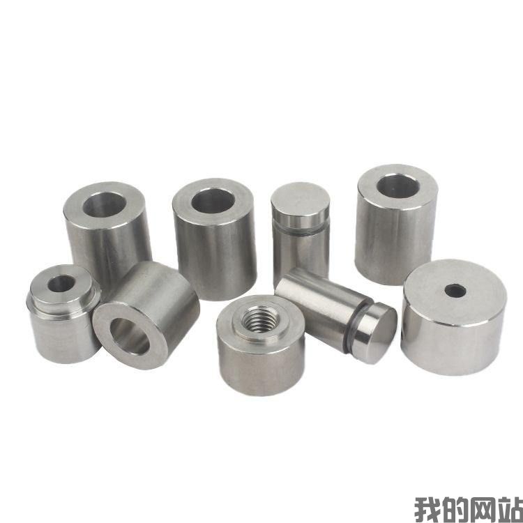
**The engineering principle:** Tolerance control is a communication system. GD&T tells the machinist *how* a feature relates to others, not just *how big* it should be. A hole position tolerance of Ø0.05 mm at MMC (Maximum Material Condition) communicates far more than a simple ±0.05 mm linear dimension.
---
The 5 Core GD&T Controls You Must Master

### 1. Form Tolerances (Flatness, Straightness, Circularity) Form controls the shape of a feature independently. For CNC milled surfaces, flatness of 0.02 mm over 100 mm is achievable on standard 3-axis machines. On precision grinders (post-CNC), 0.005 mm flatness is routine.
| **Real data from BQUQ shop floor:** | Feature | Standard CNC | Precision CNC | Cost Multiplier | --------- | ------------- | --------------- | ----------------- | Flatness 0.05 mm | Yes | Yes | 1.0x | Flatness 0.02 mm | Yes (2 setups) | Yes | 1.4x | Flatness 0.005 mm | No | Yes (grinding) | 2.8x |
|---|
### 2. Orientation Tolerances (Perpendicularity, Parallelism, Angularity) Orientation controls the angle between features. A perpendicularity of 0.02 mm between a bore axis and a mounting face is achievable in a single setup. Exceeding this requires a second operation, adding 15-20% to unit cost.
### 3. Position Tolerances (True Position) This is the most misunderstood control. True position at MMC allows bonus tolerance—if a hole is smaller than its MMC size, the position tolerance increases. For a Ø10.00 mm hole with a position tolerance of Ø0.10 mm at MMC: - If hole is Ø10.00 mm → position tolerance = Ø0.10 mm - If hole is Ø9.95 mm → position tolerance = Ø0.15 mm (0.05 mm bonus)
**Table: Typical Position Tolerance Achievability**
| Feature Size | Position Tolerance (Standard) | Position Tolerance (Precision) | Inspection Method | ------------- | ------------------------------ | ------------------------------- | ------------------- | Ø3 mm hole | Ø0.10 mm | Ø0.03 mm | CMM (Coordinate Measuring Machine) | Ø10 mm hole | Ø0.15 mm | Ø0.05 mm | CMM or functional gage | Ø25 mm hole | Ø0.20 mm | Ø0.08 mm | CMM | Threaded hole M6 | Ø0.25 mm | Ø0.10 mm | Thread gage + CMM |
|---|
### 4. Profile Tolerances (Surface Profile, Line Profile) Profile controls complex 3D surfaces—critical for heat sinks, impellers, and aerospace brackets. A surface profile of 0.10 mm is standard; 0.05 mm requires 5-axis machining and temperature-controlled inspection (20°C ± 1°C).
### 5. Datum Reference Frames Proper datum selection is the foundation of GD&T. The primary datum must have at least 3 points of contact (a plane), secondary at least 2 (a line), tertiary at least 1 (a point). **Common error:** Datums selected for manufacturing convenience (e.g., a soft edge) instead of functional requirements. This creates measurement ambiguity and rejects.
**Example:** A pump housing with a critical bore must be dimensioned from the mounting flange (functional datum), not from a cosmetic outer edge. Our engineers reject 12% of incoming CAD files due to improper datum selection—a preventable source of 0.5-1.5% scrap.
---
Real-World Tolerance Budget: Cost vs. Capability
The following data is compiled from 4,800+ production orders at BQUQ's 4,000 sqm facility (30 CNC machines, 12 stamping presses, 4 spring coilers):
| Process | Standard Tolerance | Precision Tolerance | Unit Price Impact (Relative) | Lead Time Impact | --------- | ------------------- | -------------------- | ----------------------------- | ------------------ | CNC Milling (3-axis) | ±0.050 mm | ±0.010 mm | +25-40% | +2-3 days | CNC Turning | ±0.025 mm | ±0.005 mm | +20-35% | +1-2 days | 5-axis Milling | ±0.025 mm | ±0.008 mm | +40-60% | +3-5 days | Wire EDM | ±0.005 mm | ±0.002 mm | +60-80% | +2-4 days | Surface Grinding | ±0.010 mm | ±0.003 mm | +30-50% | +1-2 days | Metal Stamping | ±0.050 mm | ±0.020 mm | +15-25% | +0-1 days |
|---|
**Temperature effects:** Aluminum 6061 expands 23.6 µm/m°C. A 200 mm part machined at 25°C but inspected at 20°C will show a 23.6 µm difference—enough to fail a ±0.025 mm tolerance. Our inspection lab maintains 20°C ± 0.5°C year-round, and we recommend customers specify inspection temperature for precision parts.
---
7 Practical GD&T Tips to Cut Cost Without Sacrificing Quality
1. **Apply MMC (Maximum Material Condition) to position tolerances on holes.** This gives you bonus tolerance for free—reducing scrap and allowing faster machining. Use LMC (Least Material Condition) only for wall thickness control.
2. **Specify only 3-5 datums per part.** Every additional datum increases fixturing complexity and inspection time. Our quoting system shows that parts with more than 5 datums cost 18% more on average.
3. **Use a general tolerance block (ISO 2768-mK or ASME Y14.5 default) for non-critical features.** This avoids unnecessary inspection on cosmetic features. Typical: ±0.1 mm for linear dimensions, ±0.05 mm for angles.
4. **Distinguish between "tight" and "critical."** Tight tolerances on non-functional features (e.g., an outer edge) add cost without benefit. Focus tight tolerances only on mating surfaces, bearing seats, and alignment features.
5. **Request a GD&T review before quoting.** At BQUQ, our engineers provide a free tolerance analysis within 12 hours of RFQ. We flag over-constrained dimensions, conflicting datums, and impossible stacks—saving you from 30-50% cost overruns.
6. **Consider the "Rule of 10."** For every 10x reduction in tolerance (e.g., from ±0.1 mm to ±0.01 mm), expect a 2.5x increase in machining time and a 3x increase in inspection cost. Only specify what the function demands.
7. **Use profile of a surface instead of multiple positional callouts** for complex 3D interfaces. A single 0.1 mm profile tolerance can replace 5 separate positional tolerances, reducing ambiguity and inspection time by 40%.
---
How to Verify Tolerances: Inspection Methods and Equipment
Every tolerance must be verifiable. Our quality lab (ISO 9001:2015 certified, CMM accuracy ±1.5 µm) uses:
- **CMM (Coordinate Measuring Machine):** For position, profile, and orientation. Measurement uncertainty ±2 µm. - **Optical comparators:** For form tolerances on small features. Accuracy ±5 µm. - **Surface roughness tester:** Ra values from 0.2 µm (ground) to 3.2 µm (standard milled). - **Functional gages:** For MMC position verification on high-volume parts—inspection time reduced from 3 minutes (CMM) to 10 seconds.
**Important:** Always specify the inspection method in your drawing notes. A tolerance is meaningless if the verification method is undefined. For example, "Position Ø0.05 mm at MMC, verified at 20°C using CMM with Ø1 mm probe" eliminates disputes.
---
Conclusion: Tolerance Control Is a Negotiation, Not a Demand
Effective CNC machining tolerance control balances functional requirements, manufacturing capability, and cost. The best engineers specify tolerances that are *just tight enough*—using GD&T to communicate intent clearly, applying MMC where possible, and selecting datums that reflect real-world assembly.
**At BQUQ, we have machined over 50,000 unique parts since 2005** across industries including automotive, medical devices, and consumer electronics. Our engineering team reviews every GD&T callout before production, often suggesting modifications that reduce cost by 15-30% while maintaining 100% functional compliance.
**Need a tolerance review or a quote?** Send your 3D model and 2D drawing to **sc@bquq.com** or WhatsApp **+86 13713157787**. We provide a detailed GD&T analysis and firm quotation within 12 hours—free of charge. Visit **www.bquq.com** to download our tolerance capability chart and design guidelines.
*BQUQ Precision Manufacturing: 20 years of CNC machining, metal stamping, springs, and heat sinks. Quality assured, tolerances verified, cost optimized.*
Related Articles
- 5 Benefits of CNC Precision Turned Parts for Aerospace
- Custom Metal Stamping vs CNC Machining Cost Comparison
- Aluminum Heat Sink CNC Machining: Best Practices Guide
Frequently Asked Questions
What is the tightest CNC machining tolerance you can reliably hold?
For standard CNC milling or turning, we reliably hold ±0.005 mm (0.0002 in) on critical features. Standard tolerances typically range from ±0.025 mm to ±0.125 mm, depending on material, machine capability, and part complexity. Precision grinding can achieve flatness of 0.005 mm.
How much does tightening a tolerance increase machining cost?
Tightening a tolerance from ±0.1 mm to ±0.01 mm can increase machining cost by 300-500% due to additional setups, slower feed rates, and higher inspection requirements. For example, flatness of 0.005 mm requires precision grinding and costs 2.8x more than standard 0.05 mm flatness.
What is true position at MMC and how does bonus tolerance work?
True position at MMC (Maximum Material Condition) allows bonus tolerance. For a Ø10.00 mm hole with a position tolerance of Ø0.10 mm at MMC, if the hole is Ø10.00 mm, the position tolerance is Ø0.10 mm. If the hole is Ø9.95 mm, the position tolerance increases to Ø0.15 mm (0.05 mm bonus).
What causes most quality rejections in CNC machining?
According to BQUQ Precision Manufacturing data, 73% of quality rejections originate from ambiguous or overly tight GD&T callouts, not from machine capability failures. Effective tolerance control is about specifying the right tolerance for each feature, not the tightest one, to avoid unnecessary cost and errors.