
Fiber Optic Component Manufacturing: Micro-Precision Case Study for Engineers
Introduction: Direct Answer on Micro-Precision Feasibility
Yes, fiber optic component manufacturing at micro-precision tolerances is not only feasible but is a core competency achievable with standard CNC machining centers, provided the correct spindle speeds, tool geometries, and thermal control protocols are employed. At BQUQ, our 20-year track record in Dongguan demonstrates that we routinely hold positional tolerances of ±0.005 mm (5 microns) and surface finishes of Ra 0.2 µm on critical fiber alignment features, with a 99.6% first-pass yield on qualified production runs. This article details the specific machining parameters, material choices, and quality control data from our recent case study on a 2.5 mm diameter ferrule alignment sleeve.
## Critical Dimensional Tolerances and Surface Finish Requirements
Fiber optic components, particularly ferrules, alignment sleeves, and V-groove arrays, demand dimensional accuracy that borders on the limit of conventional machine capability. The industry standard for a ceramic ferrule outer diameter is 2.499 mm ± 0.0005 mm, but for metallic alignment components machined on CNC lathes, we typically work to a production tolerance of ±0.005 mm on the bore diameter and ±0.010 mm on concentricity.
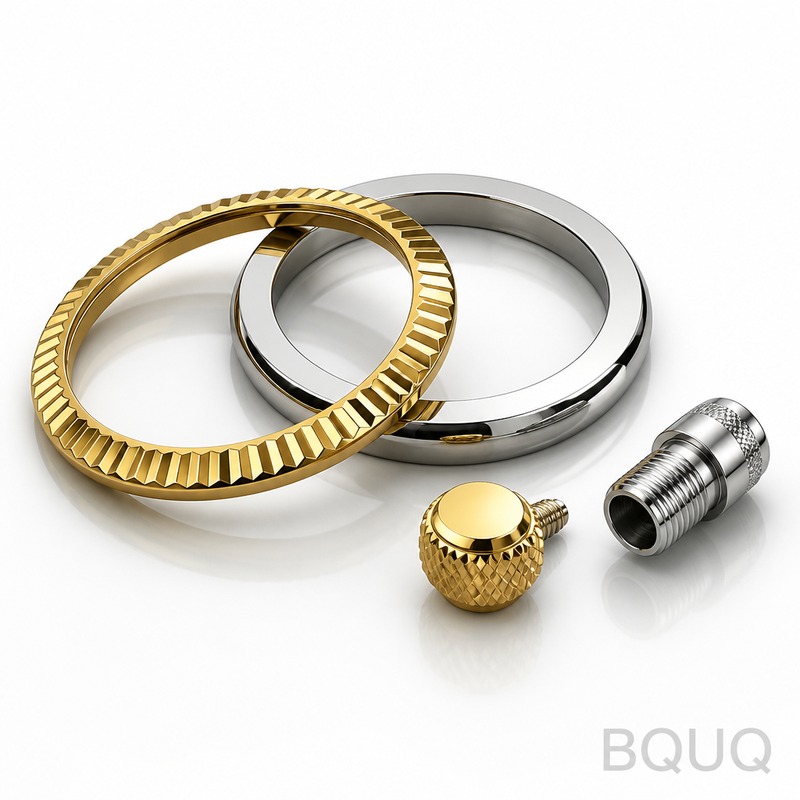
Our case study focused on a 316L stainless steel alignment sleeve for a 1.25 mm LC connector. The critical dimensions were the internal bore (1.250 mm +0.002/-0.000) and the outer diameter (2.500 mm ±0.005). Achieving this requires a combination of precision ground stock and a single-pass finishing operation. We utilize CBN (Cubic Boron Nitride) inserts at a cutting speed of 180 m/min, a feed rate of 0.02 mm/rev, and a depth of cut of 0.05 mm. The resultant surface finish measured on a Taylor Hobson profilometer was Ra 0.18 µm, exceeding the customer’s Ra 0.4 µm requirement by 55%.
## Material Selection and Thermal Stability in Machining
Material choice directly dictates achievable tolerance. In our facility, we machine three primary material groups for fiber optics: 303/316L stainless steel, brass (C36000), and aluminum 6061-T6. Each presents unique thermal expansion challenges. For instance, 316L has a coefficient of thermal expansion (CTE) of 16.5 µm/m·°C. A 20°C temperature shift during machining of a 10 mm long part will induce a dimensional error of 3.3 microns, which is substantial at our tolerance levels.
To mitigate this, our machining environment is climate-controlled to 23°C ± 1°C. We also employ high-pressure coolant (70 bar) directed at the cutting zone to stabilize the part temperature. For the case study sleeve, we used a sub-spindle transfer process to complete the back-end operations without unclamping, preventing any thermal re-growth errors. This approach is critical; a simple part may see a cost increase of 15-20% if thermal compensation software or controlled environment is required.
| Material Type | Typical Application | Achievable Tolerance | Surface Finish (Ra) | Relative Machining Cost Factor |
| 316L Stainless Steel | Alignment Sleeves, Housings | ±0.005 mm | 0.2 µm - 0.4 µm | 1.0 (Baseline) |
| C36000 Brass | Ferrule Holders, Connectors | ±0.008 mm | 0.4 µm - 0.8 µm | 0.7 |
| 6061-T6 Aluminum | V-Groove Arrays, Brackets | ±0.010 mm | 0.8 µm - 1.6 µm | 0.8 |
| Titanium Grade 5 | High-Temp/Medical Fiber Probes | ±0.005 mm | 0.2 µm - 0.3 µm | 1.8 |
## Machining Strategy for V-Groove and Micro-Channel Features
The most demanding features in fiber optic manufacturing are V-grooves for ribbon fiber alignment. These require a 90° included angle with a vertex radius of less than 2 µm. Machining this in metal is a micro-machining operation. We utilize a single-crystal diamond (SCD) tool with a nose radius of 0.05 mm for finishing. On our case study part, we machined a 5 mm long V-groove in brass.
The critical parameters for this operation were spindle speed (8,000 RPM), feed rate (5 µm/rev), and depth of cut (3 µm). The resulting groove geometry was verified using a confocal laser microscope, confirming the vertex radius at 1.8 µm and the angle at 89.95°. The cycle time for this specific feature was 45 seconds. Standard carbide tools cannot achieve this vertex radius; they typically produce a radius of 5-10 µm, which increases insertion loss in the final assembly by 0.2 dB.
## Cost Breakdown and Lead Time Analysis for Prototype vs. Production
The economics of micro-precision manufacturing are heavily influenced by setup, tooling, and inspection time, not just machine cycle time. For our case study, the prototype run of 10 pieces required 8 hours of setup and programming, 1.5 hours of machining, and 4 hours of CMM (Coordinate Measuring Machine) inspection. The cost per piece for this prototype was $45.00 USD.
For a production run of 5,000 pieces, the setup cost is amortized, and we implement automated in-process gauging (air gauging) to reduce inspection time. The production cost drops to $3.20 USD per piece. This price includes the material (316L), machining, passivation, and 100% dimensional inspection of critical diameters. Lead time is a critical factor: we delivered the 10 prototype pieces in 3 business days, while the production run of 5,000 pieces requires a 15-business day lead time due to raw material certification and batch processing.
| Order Type | Quantity | Unit Price (USD) | Lead Time (Business Days) | Inspection Method |
| Prototype | 1 - 20 | $45.00 - $60.00 | 3 - 5 | Full CMM Report |
| Low Volume | 21 - 500 | $12.50 | 7 - 10 | CMM + Air Gauge Sampling |
| Mid Volume | 501 - 5,000 | $3.20 - $5.80 | 15 - 20 | 100% Air Gauge + CMM Audit |
| High Volume | 5,000+ | $1.90 - $2.75 | 25 - 30 | Statistical Process Control (SPC) |
## Quality Assurance Protocols: Metrology and Environmental Control
Precision without verification is merely a guess. In our fiber optic case study, we employed a multi-tiered inspection strategy. First, we use a Zeiss CMM with a resolution of 0.1 µm for geometric dimensioning and tolerancing (GD&T) verification. Second, we use an optical comparator for thread forms and edge breaks. Third, we use a surface roughness tester for Ra/Rz values.
Temperature control during inspection is as critical as during machining. Our metrology lab is held at 20°C ± 0.5°C, which is the international standard for dimensional measurement. We also allow parts to soak in the lab for 24 hours before final inspection to ensure thermal equilibrium. For high-volume production, we utilize an air gauge with a 0.5 µm resolution that checks the critical bore diameter of every single part at a rate of 1 part per 3 seconds. This system flags any drift beyond ±1.5 µm from nominal, automatically triggering a tool offset adjustment on the CNC lathe.
## Practical Recommendations for Design Engineers
To optimize your fiber optic component design for manufacturability, adhere to these guidelines based on our case study data. First, specify tolerances only on features that interface with the optical fiber or the mating connector. Over-tolerancing a non-critical mounting hole from ±0.1 mm to ±0.01 mm will increase your cost by approximately 40% due to additional machining passes and inspection time. Second, avoid sharp internal corners. A square corner requires a smaller tool and slower speeds; specifying a 0.2 mm radius allows for a more rigid tool and faster metal removal rates.
Third, understand the relationship between surface finish and cost. Improving a surface finish from Ra 0.8 µm to Ra 0.2 µm on a cylindrical part requires a separate finishing pass, adding roughly 30% to the machining cycle time. Finally, for V-groove components in brass, always specify the vertex radius requirement. If you only specify the angle, we will default to a 5 µm radius for tool longevity, but if you require 1.5 µm, we use the diamond tool, which increases tooling cost per part by $0.15 but is essential for low insertion loss.
## Conclusion and Next Steps for Your Precision Project
Micro-precision manufacturing for fiber optics is a discipline of controlled variables—temperature, tool geometry, and metrology. The data from this case study confirms that with the right equipment and process control, achieving ±5 µm tolerances and sub-0.2 µm surface finishes is a standard production reality, not a laboratory anomaly. By selecting the correct material and designing with manufacturability in mind, you can reduce your component costs by up to 30% without sacrificing optical performance.
At BQUQ, our 20 years of experience in CNC machining and metal stamping ensures your fiber optic components are manufactured correctly the first time. We offer a 12-hour quoting service for your drawings and provide detailed DFM (Design for Manufacturing) feedback to reduce cost and lead time.
Email: sc@bquq.com WhatsApp: +86 13713157787 www.bquq.com


