
Heat Pipe Technology: Working Principles and Applications in Precision Manufacturing
When a heat pipe fails, your electronics overheat, your LED driver derates, and your power module shuts down. The direct answer is this: a heat pipe is a passive, two-phase heat transfer device that moves thermal energy up to 1000 times more effectively than solid copper, using evaporation and condensation within a sealed vacuum chamber. For engineers sourcing thermal solutions, understanding the capillary limit, working fluid selection, and manufacturing tolerances is the difference between a 5 W LED that lasts 50,000 hours and one that fails at 10,000 hours.
## Core Working Principle: Evaporation and Capillary Return A heat pipe operates on a closed-loop thermodynamic cycle. The pipe is a sealed copper or aluminum tube containing a small amount of working fluid (typically water, ammonia, or methanol) under vacuum. The internal wall is lined with a wick structure—either sintered powder, grooved, or mesh. When heat is applied to the evaporator section, the working fluid absorbs latent heat and vaporizes. The vapor travels rapidly to the condenser section due to the pressure differential, where it releases heat and condenses back to liquid. The capillary action of the wick then pumps the liquid back to the evaporator, completing the cycle. This process is continuous and passive, requiring no moving parts and no external power.
The effective thermal conductivity of a typical copper-water heat pipe is 50,000 to 200,000 W/m·K, versus 385 W/m·K for solid copper. This performance is achieved because latent heat transfer via phase change is far more efficient than sensible heat conduction. The operating temperature range for water-based heat pipes is 10°C to 250°C, with a maximum heat flux of approximately 500 W/cm² in the evaporator. For cryogenic applications, nitrogen-filled pipes operate from -150°C to -60°C, while liquid metal pipes (sodium, potassium) handle 400°C to 1100°C.
## Capillary Limit and Wick Structure Design The maximum heat transfer capacity of a heat pipe is governed by the capillary limit, which is the point where the wick can no longer return liquid to the evaporator fast enough to prevent dry-out. This limit is determined by the wick's pore radius, permeability, and the working fluid's surface tension. For a sintered copper wick with a pore radius of 10 microns, the capillary pressure is approximately 15 kPa. The resulting heat transport capability for a 6 mm diameter, 200 mm long heat pipe is typically 40 to 60 W. Increasing the wick thickness from 0.5 mm to 1.0 mm raises the capillary limit by 35%, but also increases thermal resistance by 0.02°C/W.
For high-power applications above 100 W, you need either a larger diameter pipe (8 mm to 10 mm) or multiple parallel heat pipes. A 10 mm diameter sintered heat pipe with a 300 mm length can handle 150 W at a 45° inclination. Grooved wicks, which have a lower capillary pressure but higher permeability, are better suited for horizontal or gravity-assisted orientations. Axial groove pipes are 20% cheaper than sintered types but have a 30% lower maximum heat flux.
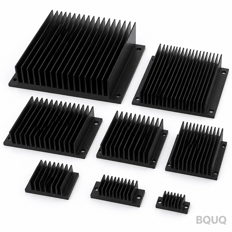
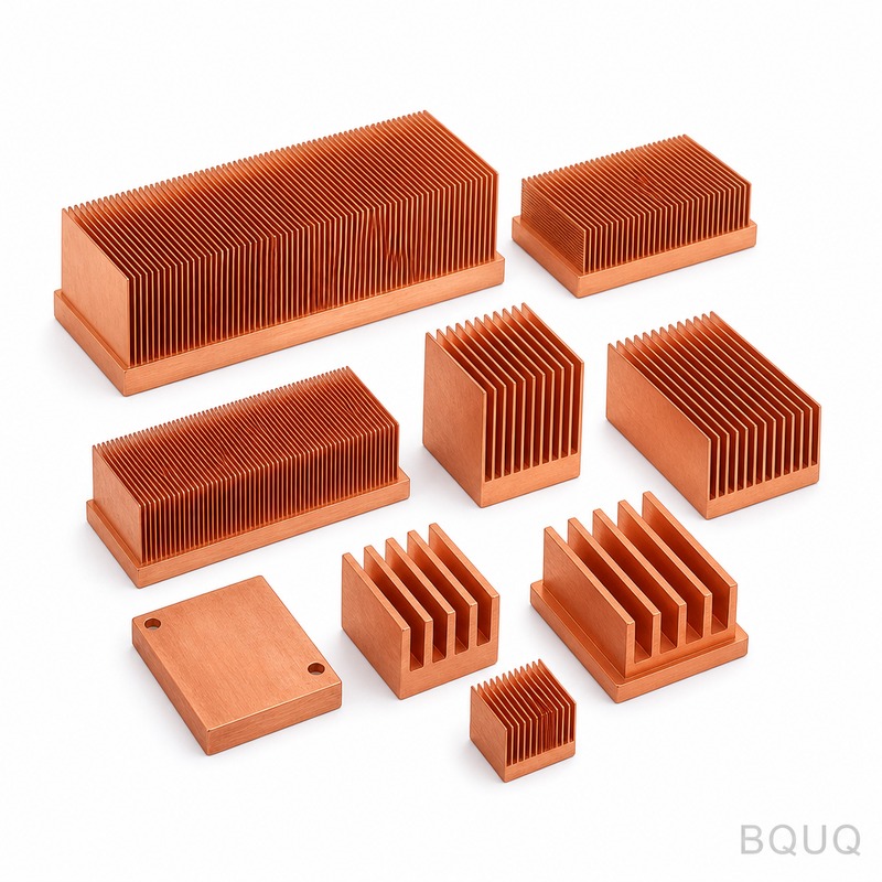
## Material Selection and Manufacturing Tolerances In CNC machining and metal stamping, heat pipes are often integrated into cold plates, heat sinks, and vapor chambers. The standard material is C1020 oxygen-free copper, with a purity of 99.95% for optimal thermal conductivity and corrosion resistance. The tube wall thickness ranges from 0.3 mm to 0.5 mm, with an outer diameter tolerance of ±0.05 mm. The total length tolerance is ±0.5 mm for straight pipes and ±1.0 mm for bent pipes.
When bending heat pipes, the minimum bend radius is 3 times the pipe diameter. For a 6 mm pipe, the minimum radius is 18 mm. A bend angle tolerance of ±2° is achievable. The flattening process can reduce the pipe thickness to 2.0 mm, but this reduces the capillary limit by 40% because the wick is compressed. For stamped heat sink bases, the press-fit pocket depth tolerance is ±0.03 mm to ensure proper thermal contact between the heat pipe and the base plate.
| Parameter | Sintered Copper Wick | Grooved Aluminum | Mesh Wick |
| Maximum Heat Flux (W/cm²) | 500 | 150 | 100 |
| Thermal Resistance (°C/W) | 0.05 | 0.12 | 0.20 |
| Minimum Bend Radius (x diameter) | 3.0 | 2.5 | 4.0 |
| Operating Temperature Range (°C) | 10 to 250 | -50 to 150 | 10 to 200 |
| Relative Cost per Unit (USD) | 2.50 | 1.80 | 1.50 |
| Typical Lifespan (hours) | 100,000 | 80,000 | 60,000 |
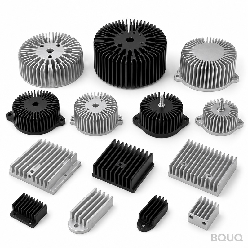
## Applications Across Industry: From LEDs to EV Batteries Heat pipes are deployed in four primary sectors: consumer electronics, automotive, telecommunications, and industrial power. In LED lighting, a single 8 mm heat pipe can manage the thermal load of a 100 W COB (chip-on-board) LED, keeping the junction temperature below 85°C at an ambient of 40°C. This extends the LED lifespan from 20,000 to 60,000 hours. In electric vehicle battery packs, flat heat pipes (2.5 mm thick) are embedded between prismatic cells to equalize temperature differences to within 3°C, which is critical for preventing thermal runaway.
Telecommunication base stations use heat pipe heat sinks with a total dissipation capacity of 800 W for 5G remote radio units. The heat pipes are oriented vertically to assist gravity, achieving a 25% improvement in thermal performance versus horizontal orientation. For industrial inverters, two-phase heat pipes with a 10 mm diameter and 400 mm length are used to transfer heat from IGBT modules to external fin stacks. The typical thermal resistance budget is 0.04°C/W for the heat pipe itself and 0.15°C/W for the fin stack. Prices for off-the-shelf heat pipe assemblies range from $3.50 to $12.00 per unit, depending on diameter, length, and wick type. Custom bent and flattened configurations cost 30% to 50% more due to tooling and inspection requirements.
## Practical Design Rules for Integration When integrating heat pipes into your product, follow these engineering rules. First, position the evaporator below the condenser for gravity-assisted operation. This can increase the capillary limit by 50%. Second, avoid sharp bends or flattening near the evaporator, as this compresses the wick and reduces performance. Third, ensure the heat pipe is in full contact with the heat source—use a thermal interface material with a minimum 3 W/m·K thermal conductivity and a tolerance of 0.05 mm for the gap. Fourth, for applications above 150°C, switch from water to methanol or acetone to prevent internal pressure buildup above 10 bar.
For vibration-prone environments, such as automotive engine bays, use sintered wick heat pipes with a mechanical shock rating of 50 G. The end caps must be welded, not crimped, to maintain vacuum integrity. Leak testing is performed with helium mass spectrometry, achieving a leak rate of less than 1 x 10⁻⁸ Pa·m³/s. The production cycle for a custom heat pipe assembly at BQUQ is typically 3 to 5 days for samples and 10 to 15 days for production runs of 1,000 units.
## FAQ: Common Engineering Mistakes and How to Avoid Them Question: Can I use a heat pipe with a 90-degree bend for a 120 W heat load? Answer: Yes, but only if you reduce the heat load to 80 W. A 90-degree bend reduces the capillary limit by 30%. Use a 10 mm diameter pipe instead of 8 mm to maintain the original capacity.
Question: What is the maximum length for a 6 mm heat pipe? Answer: The practical limit is 300 mm. Beyond this length, the vapor pressure drop reduces the effective thermal conductivity. For longer distances, use a vapor chamber or multiple heat pipes in parallel.
Question: How do I specify the flatness tolerance for a heat pipe embedded in a stamped base? Answer: The exposed surface of the heat pipe after flattening must have a flatness tolerance of 0.05 mm over 25 mm length. This ensures uniform contact with the TIM and prevents air gaps.
Question: What is the price difference between a standard and a custom heat pipe? Answer: A standard 6 mm x 200 mm sintered pipe costs $2.50. A custom bent pipe with flattening and nickel plating costs $4.20, a 68% increase. Tooling for the bending fixture is $300 to $500 one-time.
BQUQ has manufactured heat pipe assemblies and integrated heat sinks for 20 years, with CNC machining tolerances of ±0.005 mm and stamping tolerances of ±0.01 mm. Our in-house testing lab validates thermal resistance and leak integrity on every batch. For your next thermal design, request a quote with your heat load, ambient temperature, and space constraints. We provide a 12-hour quoting service with engineering feedback on feasibility and cost reduction. Email your drawings to sc@bquq.com or contact us on WhatsApp at +86 13713157787. Visit www.bquq.com for technical datasheets and case studies.


