
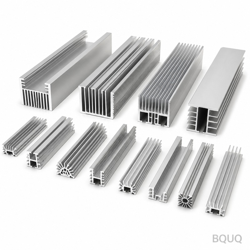
Heat Pipe Technology: Working Principles and Applications in Precision Manufacturing
Direct Answer: How Heat Pipes Work and Where They Are Used
A heat pipe is a passive, two-phase heat transfer device that moves thermal energy from a heat source to a heat sink with an effective thermal conductivity 100 to 1000 times greater than solid copper. It operates through the continuous evaporation and condensation of a working fluid within a sealed, evacuated enclosure, requiring no external power. In industrial practice, heat pipes are deployed in electronics cooling, LED lighting, heat sink assemblies, and power electronics where space constraints and high heat flux demand efficient thermal spreading.
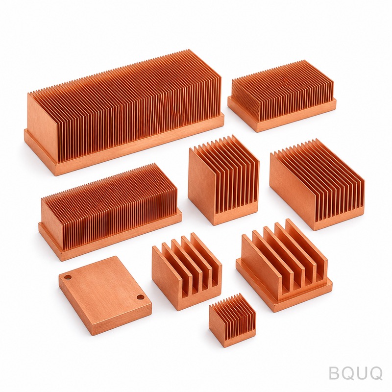
Fundamental Working Principle: The Capillary-Driven Cycle
The heat pipe consists of three primary sections: the evaporator (heat input zone), the adiabatic section (transport zone), and the condenser (heat rejection zone). The inner wall is lined with a wick structure, typically sintered copper powder, axial grooves, or mesh, which generates capillary pressure to return condensed liquid to the evaporator.
The operational cycle follows four steps. First, heat applied to the evaporator vaporizes the working fluid, absorbing latent heat of vaporization. Second, the vapor pressure difference, typically 0.1 to 1.0 kPa, drives the vapor toward the cooler condenser section. Third, the vapor condenses, releasing latent heat to the heat sink. Fourth, the wick's capillary action, generating 1 to 15 kPa of pressure, pumps the liquid back to the evaporator. This closed loop continues as long as the capillary pressure exceeds the total pressure drop from vapor flow, liquid flow, and gravitational head.
The maximum heat transport capacity is governed by several limits. The capillary limit, sonic limit, entrainment limit, boiling limit, and viscous limit each define the operational envelope. For a standard 6 mm diameter sintered heat pipe, the typical maximum heat transport capacity ranges from 20 W to 80 W at horizontal orientation, depending on working fluid and wick design.
Key Performance Parameters and Specifications
For engineering selection, five parameters define heat pipe performance. The effective thermal conductivity ranges from 5000 to 200000 W/m·K depending on length and diameter. The thermal resistance, defined as temperature difference divided by heat load, typically ranges from 0.1 to 0.5 °C/W for a 200 mm length. The operating temperature range depends on the working fluid: water operates from 10 °C to 280 °C, ammonia from -60 °C to 100 °C, and methanol from -40 °C to 120 °C.
The maximum heat flux at the evaporator surface is critical for high-power applications. Sintered wick heat pipes handle 50 to 200 W/cm², while grooved wick designs manage 10 to 50 W/cm². The axial heat flux in the vapor core ranges from 100 to 500 W/cm². The fill ratio of working fluid is typically 10 to 30% of the total internal volume.
| Parameter | Sintered Copper-Water | Grooved Aluminum-Ammonia | Mesh Copper-Water |
| Diameter range | 3 mm to 12 mm | 4 mm to 16 mm | 3 mm to 10 mm |
| Length range | 20 mm to 400 mm | 50 mm to 1200 mm | 20 mm to 300 mm |
| Max heat transport | 20 W to 80 W (6 mm OD) | 50 W to 150 W (8 mm OD) | 10 W to 40 W (6 mm OD) |
| Thermal resistance | 0.1 to 0.3 °C/W | 0.2 to 0.5 °C/W | 0.2 to 0.6 °C/W |
| Operating temp range | 10 °C to 280 °C | -60 °C to 100 °C | 10 °C to 180 °C |
| Max heat flux at evaporator | 100 to 200 W/cm² | 20 to 50 W/cm² | 30 to 80 W/cm² |
| Standard lead time | 10 to 15 days | 15 to 20 days | 10 to 15 days |
| Unit price (100 pcs, 200 mm) | USD 2.80 to 4.50 | USD 5.50 to 8.00 | USD 2.00 to 3.20 |
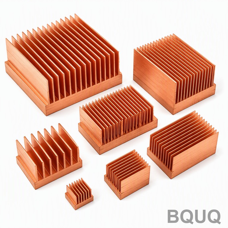
Applications in CNC Machining and Heat Sink Assemblies
In precision CNC machining, heat pipes are integrated into heat sink assemblies for high-density electronics enclosures. A typical application is a vapor chamber heat sink for a 200 W processor module, where four 6 mm heat pipes are embedded into an aluminum fin stack. The heat pipes spread heat from a 30 mm x 30 mm CPU die to a 120 mm x 120 mm fin array, reducing the die-to-ambient thermal resistance from 0.8 °C/W to 0.25 °C/W.
For industrial laser diodes, heat pipes handle heat fluxes exceeding 500 W/cm². A typical assembly uses a copper heat pipe with a sintered wick, 8 mm outer diameter and 150 mm length, embedded in a copper base plate. The system maintains the diode junction temperature below 65 °C at a 120 W heat load, with an ambient temperature of 40 °C.
In electric vehicle battery cooling, heat pipes provide passive thermal management. A 10 mm diameter grooved heat pipe with ammonia working fluid can transport 80 W over 300 mm with only a 5 °C temperature drop. This allows battery modules to operate within the optimal 20 °C to 40 °C range, extending cycle life by 15 to 20%.
Manufacturing Tolerances and Quality Control
Precision manufacturing of heat pipes requires strict dimensional control. The outer diameter tolerance for standard heat pipes is +/- 0.05 mm. The flatness of the evaporator section, when pressed into a base plate, must be within 0.03 mm over a 50 mm length. The bending radius is typically 3 times the pipe diameter for sintered wicks and 5 times the diameter for grooved wicks.
Quality control includes helium leak testing with a maximum leak rate of 1 x 10⁻⁸ Pa·m³/s. Thermal performance testing verifies that thermal resistance does not exceed the specified value by more than 5%. Life testing at 105 °C for 1000 hours confirms no non-condensable gas generation, which would degrade performance.
For CNC machining integration, the heat pipe slot in a heat sink base is machined to a width tolerance of +0.02 mm to +0.05 mm over nominal, ensuring a press-fit that maximizes thermal contact. The surface roughness of the slot is Ra 1.6 μm or better. The thermal interface material, typically a phase-change pad or solder, must have a bond line thickness of 0.05 to 0.10 mm.
Cost Considerations and Payback Analysis
The cost of integrating heat pipes into a thermal solution varies with volume and complexity. For a standard 6 mm x 200 mm sintered copper-water heat pipe, the unit cost at 500 pieces is USD 1.80 to 2.50. At 5000 pieces, the cost drops to USD 1.20 to 1.60. The total cost of a heat pipe heat sink assembly, including CNC machining, soldering, and testing, ranges from USD 8.00 to 25.00 per unit, depending on fin density and surface treatment.
The payback analysis compares heat pipe solutions against solid copper alternatives. A solid copper heat spreader of equivalent thermal performance would require 3 to 5 times the weight and 2 to 3 times the material cost. For a 200 W application, a heat pipe assembly reduces the total heat sink weight from 1.2 kg to 0.6 kg, saving USD 4.00 to 8.00 in material and shipping costs per unit.
Practical Recommendations for Engineering Integration
For optimal heat pipe performance, orient the evaporator below the condenser in gravitational assist mode, which increases heat transport capacity by 20 to 40%. When horizontal operation is unavoidable, derate the maximum heat transport capacity by 20 to 30%. For vertical operation against gravity, derate by 50 to 70%.
Ensure the heat pipe length does not exceed 400 mm for sintered wicks, as longer pipes increase vapor pressure drop and reduce capacity. Select the working fluid based on the operating temperature range, not the maximum temperature. For applications below 0 °C, use ammonia or methanol instead of water.
Design the evaporator contact area to minimize thermal resistance. The heat pipe must be flattened or machined to match the heat source footprint, with a flatness of 0.02 mm over the contact length. Apply thermal paste or solder with a thermal conductivity above 10 W/m·K to fill micro-gaps.
FAQ-Style Tips for Design Engineers
What is the minimum bend radius for a 6 mm heat pipe? For sintered wick, use 18 mm bend radius. For grooved wick, use 30 mm. Bending reduces capacity by 5 to 10% per 90-degree bend.
Can heat pipes be cut to length? No, cutting opens the sealed enclosure and destroys the vacuum. Specify exact lengths during manufacturing.
What is the typical failure mode? Non-condensable gas generation from material outgassing, which increases thermal resistance by 10 to 20% over time. This is why vacuum quality and material purity matter.
How many heat pipes are needed for a 300 W heat load? Typically 4 to 6 pipes of 6 mm diameter, or 2 to 3 pipes of 8 mm diameter, depending on heat sink fin efficiency and airflow.
Conclusion
Heat pipe technology offers a passive, reliable, and cost-effective solution for high-heat-flux thermal management in precision manufacturing. The working principle of capillary-driven two-phase heat transfer enables thermal conductivities far beyond solid materials, allowing compact heat sink designs for electronics, LED, and power systems. For engineering integration, selecting the correct wick structure, working fluid, and manufacturing tolerances is essential. BQUQ provides custom heat pipe and heat sink manufacturing with 20 years of CNC machining and metal stamping experience. For a 12-hour quotation on your thermal solution, contact us at sc@bquq.com, WhatsApp +86 13713157787, or visit www.bquq.com.


