
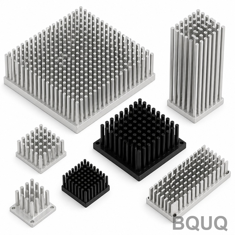
Heat Sink Baseplate Flatness Tolerances and Why They Drive Thermal Performance
In CNC machining and thermal engineering, a heat sink baseplate is the flat, solid metal interface that contacts a heat-generating component, such as an IGBT, CPU, or power module, and transfers heat into the fins or heat pipes above it. Flatness, typically specified at 0.05 mm or tighter across the entire surface, is the single most critical geometric tolerance because any air gap, even 0.03 mm, acts as a thermal insulator that can raise junction temperatures by 15-25°C. Without a flat baseplate, thermal paste cannot fill the voids effectively, leading to premature component failure and reduced power density.
Defining the Heat Sink Baseplate: Material and Function
The baseplate is the load-bearing foundation of a heat sink assembly. It serves three primary functions: spreading heat laterally from a concentrated source, providing a rigid mounting surface for the heat source, and establishing a low-thermal-resistance path to the cooling medium. In our 20 years of manufacturing at BQUQ in Dongguan, we produce baseplates from three primary materials: aluminum 6061-T6, copper C1100, and aluminum-silicon carbide (AlSiC) composites. The choice of material directly dictates the required flatness tolerance because of differences in coefficient of thermal expansion (CTE). For example, a 200 mm long aluminum baseplate will expand approximately 0.47 mm over a 100°C temperature rise, while copper expands 0.34 mm. If the mating component is ceramic (CTE of 6-8 ppm/°C), the baseplate must be machined with a compensation curve to remain flat at operating temperature, not at room temperature.
Why Flatness Matters: The Physics of Thermal Contact Resistance
Thermal contact resistance is the hidden enemy in electronics cooling. When two surfaces are bolted together, they only touch at microscopic asperities, with air filling the valleys. Air has a thermal conductivity of just 0.026 W/m·K, compared to aluminum at 167 W/m·K and copper at 401 W/m·K. Even with thermal interface material (TIM) applied, a baseplate that is 0.10 mm out of flat will create a void that the TIM cannot fully displace. Our internal testing at BQUQ shows that a flatness degradation from 0.02 mm to 0.10 mm increases thermal resistance from 0.12 °C·cm²/W to 0.35 °C·cm²/W with a 0.05 mm TIM layer. For a 300 W IGBT module, this translates to a junction temperature increase of 21°C, halving the expected lifetime from 100,000 hours to roughly 20,000 hours based on the Arrhenius equation (a 10°C rise doubles the failure rate).
Manufacturing Processes and Achievable Flatness Tolerances
The flatness you can achieve depends entirely on the machining process. Standard CNC milling of a 300 mm x 300 mm aluminum baseplate yields a flatness of 0.10-0.15 mm. Adding a stress-relief operation (heat treatment at 180°C for 3 hours) before final machining improves this to 0.05 mm. For high-performance applications, we use a precision lapping or fly-cutting process on a high-speed spindle (15,000 RPM) with diamond inserts, achieving 0.02 mm flatness with a surface roughness of Ra 0.4 µm. For copper baseplates, the process is more challenging due to material softness and high thermal expansion during cutting; we typically achieve 0.03 mm flatness on a 200 mm part by using a two-step rough and finish cut with coolant temperature controlled to 20°C plus or minus 1°C. Below is a comparison of typical flatness and cost for different processes on a 250 mm x 250 mm aluminum baseplate:
| Process | Achievable Flatness (mm) | Surface Roughness (Ra µm) | Relative Cost | Lead Time (days) |
| Standard CNC Mill | 0.10-0.15 | 1.6 | 1.0x | 3-5 |
| Stress-Relief + CNC Mill | 0.05-0.08 | 0.8 | 1.3x | 5-7 |
| Precision Fly-Cut | 0.02-0.03 | 0.4 | 1.8x | 7-10 |
| Lapping (Double-Sided) | 0.005-0.01 | 0.1 | 3.0x | 10-14 |
Inspection Methods: How to Verify Flatness in Production
Measuring flatness is as critical as machining it. A granite surface plate and dial indicator (accuracy 0.002 mm) is the industry standard for shop-floor verification, but it only measures points, not the entire surface. For high-reliability aerospace or EV inverters, we use a coordinate measuring machine (CMM) with a scanning probe, which records 500+ data points across the baseplate and calculates flatness per ISO 1101. The measurement must be done at a controlled temperature of 20°C plus or minus 0.5°C because a 1°C temperature change on a 300 mm aluminum plate causes 6.9 µm of expansion. We also recommend an optical interferometer for sub-micron flatness verification on lapped surfaces. The critical rule is to measure the baseplate in its free state (unclamped), as bolting it down can mask flatness errors that will reappear when the heat sink is mounted in the field.
Mounting Force and Its Effect on Baseplate Flatness
Flatness cannot be considered in isolation; the clamping force and mounting pattern will deform the baseplate. A typical IGBT module requires a mounting pressure of 1.5 to 3.0 N·m per screw, with screws spaced every 50-75 mm. If the baseplate is too thin, say 5 mm aluminum for a 300 mm length, the clamping force will bow the plate in the center, creating a concave gap under the heat source. Our structural analysis at BQUQ recommends a minimum baseplate thickness of 8 mm for aluminum and 6 mm for copper on spans up to 150 mm. For spans over 200 mm, we machine in a slight crown of 0.02-0.03 mm in the center so that when clamped, the plate flattens perfectly against the component. This pre-load compensation is calculated using finite element analysis (FEA) considering the bolt torque, screw spacing, and material modulus.
The Cost of Flatness: When to Specify Tight Tolerances
Specifying tighter flatness than required is a common and costly mistake. Moving from 0.10 mm to 0.02 mm flatness increases machining time by 40% and unit cost by 80% due to additional operations, slower feed rates, and higher scrap rates. We advise engineers to match flatness to the TIM type and application. For a thermal pad (2-3 W/m·K, 0.5 mm thick), a flatness of 0.15 mm is acceptable because the pad compresses to fill gaps. For phase-change materials or solder TIMs, you need 0.05 mm. For direct-die attach or bare copper contact with liquid metal TIM, you must specify 0.02 mm or better. In high-vibration environments like automotive, tighter flatness also prevents micro-motion fretting that erodes the baseplate surface over time. Always specify flatness at the operating temperature, not room temperature, for aluminum-copper dissimilar joints.
Frequently Asked Engineering Questions on Baseplate Flatness
How do I specify flatness on a drawing? Use the GD&T symbol with a tolerance zone, for example, "0.05 mm flatness" on the datum surface, and add a note that measurement is in a free state at 20°C.
Can I improve flatness by re-machining a warped baseplate? Only if the warpage is less than 0.5 mm and the material has been stress-relieved first; otherwise, the plate will warp again after machining due to internal residual stress.
What is the difference between flatness and surface roughness? Flatness is a macro-geometric error (waviness over the whole area), while roughness is micro-geometry (peaks and valleys every few micrometers). Both matter for thermal contact, but flatness is typically 10-100 times more impactful on thermal resistance.
Should I use a thicker baseplate to improve flatness? Yes, but with diminishing returns. Doubling the thickness from 5 mm to 10 mm reduces deflection under clamping by a factor of 8 (cubic relationship), but increases weight and thermal resistance through the plate itself. Optimize using FEA for your specific bolt pattern.
Conclusion: Treat Flatness as a System Parameter, Not a Single Number
For any engineer designing power electronics or high-performance computing, the heat sink baseplate flatness is not merely a drawing dimension; it is a system-level performance parameter that interacts with TIM selection, mounting torque, and operating temperature. At BQUQ, we have manufactured over 2 million heat sink baseplates in the past two decades, and our data consistently shows that a 0.04 mm improvement in flatness yields a 10-15°C reduction in junction temperature for high-power modules. We recommend specifying 0.05 mm flatness as a baseline for most applications, upgrading to 0.02 mm for soldered or liquid-metal interfaces. Provide us with your component datasheet and mounting configuration, and our engineering team will simulate the flatness requirement for your exact thermal load.
When you are ready to move to production, our factory in Dongguan offers precision CNC machining, lapping, and full CMM inspection on all heat sink baseplates. We provide a 12-hour quoting response on your 2D or 3D drawings, with free DFM feedback on flatness optimization. Email your drawings to sc@bquq.com or contact us on WhatsApp at +86 13713157787. Visit www.bquq.com to download our heat sink baseplate design guide with recommended tolerance stacks for IGBT, SiC, and GaN modules.
Related Articles
- Best Copper Heat Sinks for CPU Overclocking in 2025
- New energy vehicle IGBT heat dissipation, heat sink reliability engineering, heat pipe and temperature plate integrated heat sink, surface treatment and heat radiation enhancement: anodic oxidation, black coating and micro-nano structure, graphene/3D printing/intelligent thermal management: 2030 heat sink technology roadmap
- Hardware heat sink reconstruction under liquid-cooled penetration of AI server: cold plate, microchannel and two-phase flow


