
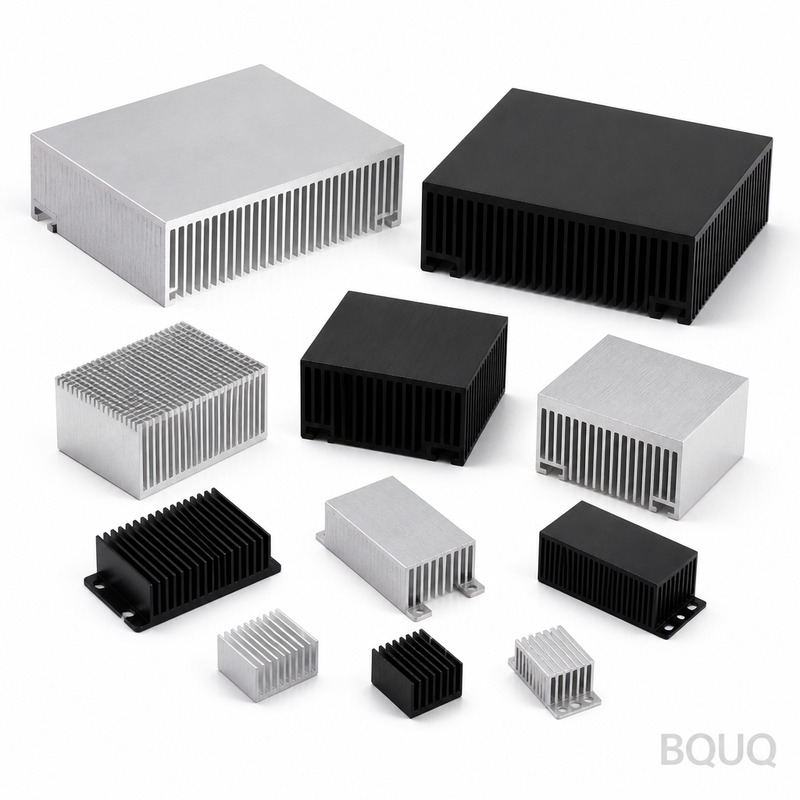
Heat Sink Baseplate Flatness: Why It Matters for Thermal Performance
Direct Answer: What Is a Heat Sink Baseplate and Why Does Flatness Matter?
A heat sink baseplate is the solid metal foundation of a heat sink assembly that contacts the heat source (CPU, IGBT, or power module) and spreads thermal energy into the fins. Flatness matters because any deviation from a perfectly planar surface creates microscopic air gaps that act as thermal insulators, increasing thermal resistance by 15% to 40% depending on the gap size. For high-power electronics, a baseplate flatness of 0.05 mm or better across a 100 mm surface is the difference between a junction temperature of 85°C and 105°C, directly impacting component lifespan and system reliability.
Baseplate Function and Material Selection
The baseplate serves three critical functions: thermal spreading, structural support, and interface compatibility. It receives heat from a semiconductor device, spreads it laterally across a larger area, and transfers it to the fin array where convection removes it. The baseplate material must balance thermal conductivity, coefficient of thermal expansion (CTE), weight, and cost.
Aluminum 6061-T6 is the industry standard for most applications, offering a thermal conductivity of 167 W/m·K and a CTE of 23.6 ppm/°C. Copper C11000 provides 401 W/m·K but has a CTE of 17.0 ppm/°C, which can cause stress mismatch with ceramic substrates. For high-end applications requiring CTE matching to silicon (2.6 ppm/°C) or SiC (4.0 ppm/°C), copper-molybdenum (CuMo) or aluminum silicon carbide (AlSiC) composites are used despite their higher cost.
| Material | Thermal Conductivity (W/m·K) | CTE (ppm/°C) | Density (g/cm³) | Relative Cost | Typical Application |
| Aluminum 6061-T6 | 167 | 23.6 | 2.70 | 1.0x | Standard air-cooled heat sinks |
| Copper C11000 | 401 | 17.0 | 8.89 | 3.5x | High-power IGBT modules |
| AlSiC (30% SiC) | 180 | 8.0 | 2.90 | 8.0x | Aerospace, EV inverters |
| CuMo (15% Cu) | 180 | 7.0 | 9.30 | 12.0x | Military radar, laser diodes |
The thermal conductivity difference between aluminum and copper means that for the same heat load, a copper baseplate can be 40% thinner while achieving the same spreading resistance. However, the CTE mismatch between copper and ceramic substrates (like Al₂O₃ or AlN) can cause solder joint fatigue after 5,000 to 10,000 thermal cycles. This is why many power electronics manufacturers choose AlSiC despite its lower conductivity, as the reduced thermal stress extends device lifetime by 3x to 5x.
Flatness Specifications and Measurement Standards
Flatness is defined as the deviation of a surface from a perfect plane, measured in millimeters or microns. For heat sink baseplates, the critical measurement is the maximum peak-to-valley deviation across the entire contact area. The measurement is typically performed using a coordinate measuring machine (CMM) with a resolution of 0.001 mm, or a laser interferometer for ultra-flat surfaces.
The required flatness depends on the interface material and the size of the baseplate. Thermal interface materials (TIMs) like grease, phase change materials, or graphite pads have different gap-filling capabilities. Standard silicone grease can fill gaps up to 0.10 mm, but the thermal conductivity of the grease layer (0.5 to 3.0 W/m·K) is far lower than solid metal, so minimizing the gap is essential.
| Baseplate Size | Standard Flatness (mm) | Precision Flatness (mm) | Corresponding TIM Thickness (mm) |
| 50 x 50 mm | 0.10 | 0.03 | 0.05 - 0.08 |
| 100 x 100 mm | 0.15 | 0.05 | 0.08 - 0.12 |
| 200 x 200 mm | 0.25 | 0.08 | 0.12 - 0.18 |
| 300 x 300 mm | 0.40 | 0.12 | 0.18 - 0.25 |
For a 100 x 100 mm baseplate, going from 0.15 mm flatness to 0.05 mm flatness reduces the required TIM thickness from 0.12 mm to 0.08 mm. This 0.04 mm reduction in TIM thickness can lower the thermal resistance by 0.02°C/W. For a 300 W heat source, this translates to a 6°C lower junction temperature, which can extend capacitor and semiconductor lifetime by approximately 30% (based on the Arrhenius equation, every 10°C reduction doubles lifetime).
Manufacturing Processes and Achievable Flatness
The manufacturing process determines the achievable flatness and the associated cost. As-cast aluminum baseplates typically have poor flatness (0.5 mm or worse) due to residual stress relief and uneven cooling. Secondary machining operations are required to achieve specification.
CNC milling is the most common method for producing precision baseplates. A single-pass finish cut with a fly cutter or face mill can achieve flatness of 0.05 mm on a 150 x 150 mm surface. The key parameters are spindle speed (8,000 to 12,000 RPM), feed rate (1,500 to 2,500 mm/min), and depth of cut (0.10 mm for finish pass). Stress relief before final machining is critical; a thermal stress relief cycle at 190°C for 2 hours reduces residual stress by up to 70% and prevents post-machining warpage.
Lapping and grinding are used for ultra-flat surfaces. Lapping with 9-micron aluminum oxide abrasive can achieve 0.01 mm flatness, but this process adds 0.50 to 2.50 USD per part depending on size. Precision grinding with a diamond wheel achieves 0.02 mm but requires a stiff machine setup to avoid thermal distortion.
| Process | Achievable Flatness (mm/100mm) | Surface Roughness (Ra, µm) | Cost Premium per Part | Lead Time Impact |
| Extrusion + as-cut | 0.30 | 3.2 | Base | None |
| CNC Milling (finish) | 0.05 | 1.6 | +20% to 40% | +1 to 2 days |
| Precision Grinding | 0.02 | 0.8 | +50% to 80% | +3 to 4 days |
| Lapping | 0.01 | 0.4 | +100% to 150% | +5 to 7 days |
For production volumes above 5,000 units per month, CNC machining with a dedicated fixture is the most cost-effective approach. The fixture must support the baseplate uniformly to prevent deflection during cutting. Using vacuum chucks or honeycomb support plates reduces deflection by 60% compared to standard vises.
Thermal Resistance and Flatness Relationship
The thermal interface resistance (R_tim) is directly proportional to the TIM thickness and inversely proportional to the TIM thermal conductivity. For a given clamp pressure (typically 10 to 30 psi), the TIM thickness is determined by the combined flatness of the baseplate and the device package.
The equation R_tim = t / (k_tim × A) shows that a 0.05 mm increase in TIM thickness on a 100 x 100 mm baseplate with grease (k = 1.0 W/m·K) adds 0.005°C/W. While this seems small, consider a module dissipating 500 W. The temperature rise becomes 2.5°C. Over a 24/7 operation, this 2.5°C increase accelerates the aging of electrolytic capacitors by 15% and can reduce LED lumen maintenance from 90% to 85% after 50,000 hours.
The clamping force also interacts with flatness. If the baseplate has a convex shape (high in the center), the clamping force concentrates at the edges, leaving a larger gap in the center. Conversely, a concave shape concentrates force in the center, extruding the TIM outward. Studies have shown that a convex baseplate of 0.08 mm deviation can cause a 25% increase in thermal resistance compared to a perfectly flat plate under the same torque conditions.
Practical Recommendations for Design and Procurement
When specifying a heat sink baseplate, focus on three parameters: flatness, surface roughness, and material. For most commercial applications, a flatness of 0.10 mm per 100 mm is adequate when using a high-quality phase-change TIM (k = 3.0 W/m·K). For automotive or industrial applications subject to vibration and thermal cycling, specify 0.05 mm per 100 mm and require a stress-relieved material.
Request a flatness inspection report from your supplier for each lot. The report should include the measurement method (CMM with 0.001 mm resolution), the number of measurement points (minimum 9 points for a 100 mm square), and the maximum deviation recorded. BQUQ provides a free flatness verification service with every prototype order, including a digital copy of the CMM data.
Consider the interface material early in the design. If you plan to use a graphite pad (0.05 mm thick), the baseplate flatness must be better than 0.03 mm per 100 mm to avoid tearing the pad. If using liquid metal TIM (k = 40 W/m·K), the flatness requirement can relax to 0.15 mm, but the surface must be nickel-plated to prevent galvanic corrosion.
FAQ-Style Tips on Baseplate Flatness
What is the acceptable flatness for a CPU heat sink baseplate? For standard desktop CPUs with an integrated heat spreader (IHS), the baseplate flatness should be 0.08 mm or better across the 40 x 40 mm contact area. Most quality aftermarket coolers achieve 0.05 mm.
How do I measure flatness without a CMM? Use a precision straight edge and feeler gauges. Place the straight edge across the baseplate and attempt to insert a 0.05 mm feeler gauge at various points. If it fits, the flatness is worse than 0.05 mm. This method has an uncertainty of approximately 0.02 mm but is adequate for quick field checks.
Does lapping a baseplate improve performance? Lapping removes machining marks and reduces surface roughness, but it does not fix warpage. If your baseplate is warped (exceeding 0.10 mm), lapping will just create a smooth but still non-flat surface. The correct fix is re-machining with proper stress relief.
Why does my baseplate become non-flat after mounting? Differential thermal expansion between the baseplate (aluminum) and the PCB or frame (FR4) can cause bowing. Use a compliant TIM (silicone pad, 0.25 mm thick) to accommodate this movement, or specify a baseplate material with CTE closer to the mounting structure.
Conclusion and Engineering Summary
The heat sink baseplate is not just a mounting plate; it is a critical thermal component that determines the efficiency of heat transfer from the device to the fins. Flatness of 0.05 mm per 100 mm is the practical threshold for high-performance applications, while 0.10 mm is acceptable for standard commercial use. The cost difference between these two specifications is typically 15% to 25% of the baseplate machining cost, which is a small price for a 5 to 10°C improvement in junction temperature. Always pair the flatness specification with an appropriate TIM and clamping design to achieve the calculated thermal performance.
Get a Precision Quote Within 12 Hours
BQUQ operates CNC machining, metal stamping, and heat sink assembly lines in Dongguan, China with 20 years of manufacturing experience. We machine baseplates to 0.01 mm flatness with CMM verification on every lot. Send your CAD file or drawing for a free flatness analysis and quotation. Our engineering team will respond within 12 hours with DFM feedback and pricing.
Email: sc@bquq.com WhatsApp: +86 13713157787 Website: www.bquq.com
Related Articles
- Best Copper Heat Sinks for CPU Overclocking in 2025
- 5G Base Station Outdoor AAU Cooling: The Climate Adaptation Challenge of Fanless Passive Design
- Hardware heat sink reconstruction under liquid-cooled penetration of AI server: cold plate, microchannel and two-phase flow
Frequently Asked Questions
What is a heat sink baseplate and why is flatness so important?
A heat sink baseplate is the solid metal foundation that contacts the heat source and spreads thermal energy into the fins. Flatness matters because deviations create microscopic air gaps that act as thermal insulators, increasing thermal resistance by 15% to 40%. For high-power electronics, a flatness of 0.05 mm or better across a 100 mm surface can mean the difference between a junction temperature of 85°C and 105°C.
What materials are commonly used for heat sink baseplates and what are their trade-offs?
Aluminum 6061-T6 is the industry standard with 167 W/m·K thermal conductivity and a CTE of 23.6 ppm/°C. Copper C11000 offers 401 W/m·K but has a CTE of 17.0 ppm/°C, which can cause stress mismatch with ceramic substrates. For CTE matching to silicon or SiC, CuMo or AlSiC composites are used despite higher costs. Copper can be 40% thinner than aluminum for the same spreading resistance.
How does CTE mismatch affect baseplate reliability in thermal cycling?
CTE mismatch between copper and ceramic substrates can cause solder joint fatigue after 5,000 to 10,000 thermal cycles. This is why many power electronics manufacturers choose AlSiC despite its lower conductivity of 180 W/m·K compared to copper's 401 W/m·K. The reduced thermal stress from AlSiC's CTE of 8.0 ppm/°C extends device lifetime by 3x to 5x compared to copper.
How is baseplate flatness measured and what standards apply?
Flatness is measured as the maximum peak-to-valley deviation across the entire contact area. Measurements are typically performed using a coordinate measuring machine (CMM) with a resolution of 0.001 mm, or a laser interferometer for ultra-flat surfaces. The required flatness depends on the interface material and baseplate size, with 0.05 mm or better across a 100 mm surface being critical for high-power electronics.


