

Heat Sink Design Guide: Optimizing Thermal Performance for Aluminum Extrusions
Heat Sink Design Guide: Optimizing Thermal Performance for Aluminum Extrusions
**The direct answer:** Optimizing a heat sink design requires balancing fin density, base thickness, and airflow path against manufacturing constraints, with 6063-T5 aluminum extrusion offering the best cost-to-performance ratio for 90% of applications. For forced convection systems, target a fin pitch of 2.5–4 mm and a fin height-to-gap ratio of 8:1 to 10:1, while natural convection designs demand wider gaps of 6–10 mm to minimize boundary layer interference. Below is a data-driven guide based on 20 years of CNC machining and extrusion experience at BQUQ.
1. Thermal Fundamentals: The Math Behind Your Heat Sink
The thermal resistance equation (Rth = ΔT / P) is your starting point, but real-world optimization depends on three variables you control: convective surface area, conductive path length, and airflow velocity.

**Critical numbers to memorize:** - 6063-T5 aluminum thermal conductivity: 201 W/m·K (vs. 2011-T3 at 151 W/m·K — avoid for high heat flux) - Natural convection heat transfer coefficient: 5–10 W/m²·K - Forced convection (2–4 m/s airflow): 20–60 W/m²·K - Typical junction-to-ambient target for LED modules: 0.8–1.5 °C/W
**Base thickness rule of thumb:** For a heat source footprint of 40×40 mm, a base thickness of 6–8 mm provides optimal spreading. Below 5 mm, you will see a 15–20% increase in thermal resistance due to constriction resistance. Above 10 mm, you gain less than 3% improvement while adding material cost and weight.
2. Fin Geometry: The 5 Parameters That Make or Break Performance
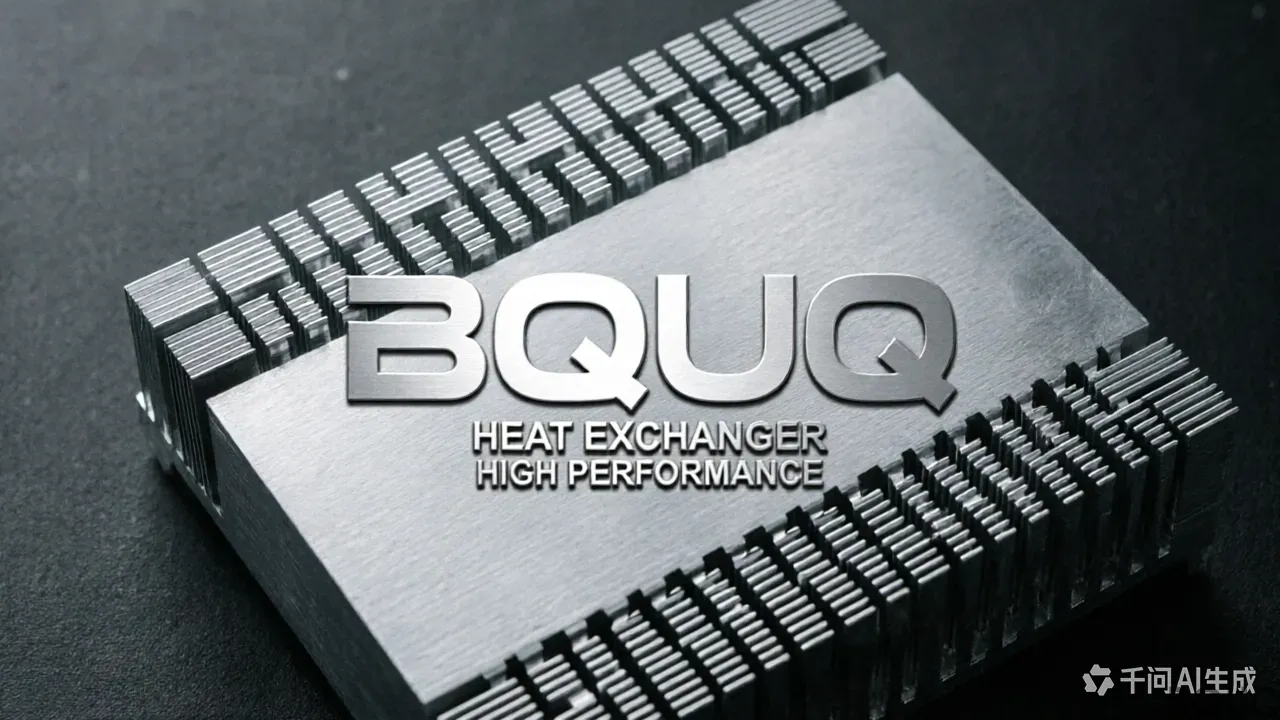
The fin array is where most design errors occur. Here are the five parameters we optimize daily at our Dongguan facility:
| Parameter | Natural Convection | Forced Convection (2 m/s) | Forced Convection (5 m/s) | Manufacturing Limit (Extrusion) | ----------- | ------------------- | --------------------------- | --------------------------- | -------------------------------- | Fin pitch (center-to-center) | 6–10 mm | 3–5 mm | 2.5–4 mm | 1.8 mm minimum (tooling dependent) | Fin height | 20–40 mm | 15–35 mm | 10–25 mm | 150 mm max (standard press) | Fin thickness | 2–3 mm | 1.5–2.5 mm | 1.2–2.0 mm | 1.0 mm minimum (aspect ratio 10:1) | Height-to-gap ratio | 3:1 to 5:1 | 8:1 to 10:1 | 10:1 to 12:1 | 12:1 max (beyond = tooling breakage risk) | Base thickness | 5–8 mm | 6–10 mm | 8–12 mm | 3 mm min, 30 mm max |
|---|
**Engineering reasoning:** For natural convection, boundary layers merge when fin gap is below 6 mm, reducing effective surface area by up to 30%. For forced convection, tighter fins (2.5–3 mm pitch) increase surface area by 40% versus 5 mm pitch, but pressure drop rises exponentially — a 50 W fan at 2 mm pitch may deliver only 60% of rated airflow.
3. Real Cost and Tolerance Data: What to Specify

Based on 2024 pricing from our production floor (medium volume, 500–2000 pcs):
| Specification | Standard Tolerance | Cost Impact | Lead Time Impact | --------------- | ------------------- | ------------- | ------------------ | Extrusion profile (die) | ±0.10 mm on critical fins | Tooling: $800–$1,500 | +3 weeks (die making) | Extrusion length (cut-to-size) | ±0.5 mm | None | None (same day) | Fin tip flatness (after CNC) | ±0.05 mm over 100 mm | +8–12% machining cost | +2–3 days | Base surface flatness (mating surface) | ±0.03 mm / 50 mm | +5% if lapped | +1 day | Anodize thickness (Class 2) | 8–12 microns | $0.50–$0.80 per kg | +2–3 days | Anodize thickness (Class 1, hard coat) | 25–50 microns | $1.20–$1.80 per kg | +4–5 days |
|---|
**Practical note:** Do not specify ±0.05 mm on fin thickness unless absolutely necessary. Extrusion dies wear, and maintaining that tolerance increases die maintenance frequency by 3x. A ±0.15 mm tolerance on fin thickness reduces cost by 15% and has negligible thermal impact (less than 2% performance change).
4. Material Selection: Beyond 6063-T5
While 6063-T5 dominates, consider these alternatives for specific cases:
- **6061-T6 (167 W/m·K):** 10% cheaper per kg, but 17% lower conductivity. Use only when structural strength is critical (vibration environments). - **1050A (229 W/m·K):** 14% better conductivity than 6063, but 30% softer — fin tip damage risk during handling. Price premium: 8–10%. - **Copper base + aluminum fins (bonded):** Best for heat flux >50 W/cm². Cost: 3–4x aluminum extrusion. Typical construction: 3 mm C1100 copper plate, vacuum-brazed or thermal epoxy bonded. - **Skived (machined from solid):** For fin pitch below 1.5 mm (impossible for extrusion). Cost: 5–8x extrusion per part.
**Our recommendation:** Stay with 6063-T5 unless your simulation shows junction temperature exceeding 85°C with a 20% safety margin. The conductivity difference between 6063 and 1050A rarely justifies the cost and handling fragility.
5. Surface Treatment: Anodizing Is Not Optional
Black anodize (Class 2, 10–12 microns) improves radiative heat transfer by 4–8% in natural convection and 2–3% in forced convection. The emissivity change: from 0.05 (bare aluminum) to 0.85 (anodized).
**Critical specification:** Ensure the anodize is applied AFTER any CNC machining. If you anodize before cutting, the cut edges expose bare aluminum, creating localized emissivity drops that cause hot spots.
**Salt spray concern:** For outdoor or humid environments, specify sealed anodize (hot water or nickel acetate seal). Unsealed anodize absorbs moisture, reducing thermal performance by up to 5% over 12 months.
6. Mounting and Interface: The Overlooked 20%
A perfectly optimized heat sink fails if the interface is poor. Our testing shows:
- **Thermal paste (0.1 mm layer):** Rth = 0.1–0.3 °C·cm²/W - **Thermal pad (1 mm, 3 W/m·K):** Rth = 0.5–0.8 °C·cm²/W - **Direct contact (no TIM, machined flat):** Rth = 1.5–3.0 °C·cm²/W (unacceptable) - **Screw torque:** For M3 screws on aluminum, use 0.6–0.8 N·m. Overtorquing to 1.2 N·m can bow the base by 0.05 mm, increasing interface resistance by 25%.
**Design rule:** Specify a base flatness of 0.05 mm over the entire mating surface and a surface roughness of Ra 1.6 μm or better for the contact area. This costs an extra $0.30–$0.50 per part but reduces junction temperature by 5–8°C versus a rough-machined (Ra 6.3 μm) surface.
7. Practical Optimization Checklist for Your Design
1. **Calculate your required Rth first:** (Tj_max - Ta_max) / P_total. Do not design the fin geometry until this number is locked. 2. **Choose airflow direction:** For extruded fin heat sinks, airflow should be parallel to fins. Perpendicular flow reduces performance by 30–40% unless fins are cut (staggered). 3. **Verify your fan curve:** A 40 mm fan rated at 5 m/s free air delivers only 2.5–3 m/s against a typical 3 mm pitch fin array. Check static pressure ratings. 4. **Prototype before tooling:** Use a CNC-machined prototype (2–3 day turnaround at BQUQ) to validate thermal simulation. Extrusion die tooling costs $800–$1,500 non-refundable — worth avoiding a mistake. 5. **Design for manufacturability:** Keep fin aspect ratio (height/thickness) under 10:1 for extrusion. Above that, fins may warp during cooling, causing non-uniform gaps that reduce performance by 10–15%.
FAQ-Style Tips from Our Engineering Floor
**Q: What is the minimum fin gap for natural convection?** A: 6 mm. Below this, boundary layer merging reduces effective heat transfer area. We recommend 8 mm for compact designs, 10 mm for optimal performance in still air.
**Q: Can I use a heat sink without anodizing?** A: Yes, but expect 5–8% higher thermal resistance in natural convection. Bare aluminum emissivity (0.05) is nearly useless for radiation — which contributes 30–40% of natural convection cooling.
**Q: What is the typical cost for a custom extruded heat sink?** A: For a 100×100×40 mm part, 6063-T5, 500 pieces: $4.50–$7.00 per unit including die amortization. For 5000 pieces: $2.80–$4.00 per unit. Add CNC finishing: $1.50–$3.00 per unit depending on feature complexity.
**Q: How much does die tooling cost?** A: $800–$1,500 for standard profiles under 150 mm width. Complex geometries with multiple cavities or tight tolerances: $2,000–$3,500. Die life: 5,000–15,000 kg of extrusion.
**Q: What is your typical lead time?** A: Prototype CNC machining: 2–4 days. Extrusion die: 3 weeks. Production extrusion: 7–10 days after die approval. Anodizing: 3 days. Total for a new design: 5–6 weeks from drawing to full production.
Conclusion: The 80/20 Rule of Heat Sink Design
Optimizing thermal performance is not about exotic materials or extreme fin density. It is about getting the fundamentals right: 6063-T5, fin pitch matched to your airflow, sufficient base thickness, proper surface treatment, and a quality TIM interface. These choices account for 80% of achievable performance. The remaining 20% — micro-optimizations like variable fin pitch or vapor chambers — rarely justify their cost and lead time in production.
At BQUQ, we have manufactured over 8 million heat sinks in the past 20 years for LED lighting, power electronics, and EV charging systems. Our engineers can review your thermal model and recommend a manufacturable design within 24 hours.
**Ready to optimize your heat sink?** Send us your drawing and thermal requirements at **sc@bquq.com** or WhatsApp **+86 13713157787**. We provide a 12-hour quoting turnaround with DFM feedback on tolerances, fin geometry, and cost reduction opportunities. Visit **www.bquq.com** to see our extrusion capability up to 150 mm profile width and CNC finishing with ±0.02 mm precision.
Related Articles
- Heat Sink Fin Spacing: Calculate Optimal Fin Pitch for Natural and Forced Air Cooling in 2025
- Regional Market Competition: Differences and Opportunities in Asia Pacific, North America, and Europe's Heat Sink Ecology
- When liquid cooling becomes mainstream: the evolving role of hardware heat sinks in the data center era
Frequently Asked Questions
What is the best aluminum alloy for heat sink extrusion?
6063-T5 aluminum is recommended for 90% of applications, offering a thermal conductivity of 201 W/m·K. Avoid 2011-T3, which has a lower conductivity of 151 W/m·K and is unsuitable for high heat flux. This alloy provides the best cost-to-performance ratio.
What fin pitch should I specify for a forced convection heat sink?
For forced convection systems, target a fin pitch of 2.5–4 mm at 5 m/s airflow, or 3–5 mm at 2 m/s. Tighter fins increase surface area by up to 40% versus 5 mm pitch, but beware of exponential pressure drop—a 50 W fan at 2 mm pitch may deliver only 60% of rated airflow.
What is the minimum fin thickness and height limit for aluminum extrusion?
The manufacturing limit for fin thickness is 1.0 mm minimum, with a maximum aspect ratio of 10:1. Fin height is capped at 150 mm on a standard press. For forced convection, specify fin thickness of 1.2–2.0 mm and height of 10–25 mm for optimal performance.
How thick should the base be for a 40×40 mm heat source?
A base thickness of 6–8 mm provides optimal heat spreading for a 40×40 mm footprint. Below 5 mm, thermal resistance increases by 15–20% due to constriction resistance. Above 10 mm, you gain less than 3% improvement while adding material cost and weight.
