
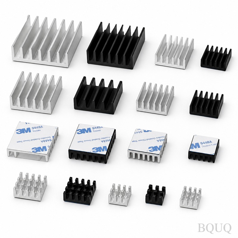
Heat Sink Design Guide: Optimizing Thermal Performance for CNC Machined Components
The direct answer to optimizing heat sink thermal performance is to maximize surface area while minimizing thermal resistance from the heat source to the ambient air, achieved through material selection, fin geometry optimization, and surface treatment. For CNC machined aluminum heat sinks, the most effective balance between cost and performance is achieved with 6061-T6 or 6063-T5 aluminum, fin thickness of 1.2 mm to 2.0 mm, and a base plate thickness of 5 mm to 8 mm. This guide provides specific, measurable parameters based on our 20 years of manufacturing experience in Dongguan, China.
Material Selection and Thermal Conductivity
The choice of material determines the upper limit of thermal performance. Pure copper (C11000) offers 398 W/mK thermal conductivity, while aluminum alloys range from 150 to 210 W/mK. However, the density ratio (copper is 3.3 times heavier) and cost ratio (copper is 4 to 6 times more expensive per kilogram) make aluminum the default choice for most applications.
For CNC machining, 6063-T5 aluminum provides 201 W/mK thermal conductivity and superior extrudability, but 6061-T6 offers better machinability and structural strength at 167 W/mK. When weight is critical, such as in aerospace or automotive electronics, consider 6061-T6 with a hard anodized coating (50 to 100 microns) which adds 0.5 to 1.0 degree Celsius thermal resistance but improves corrosion resistance.
| Material | Thermal Conductivity (W/mK) | Density (g/cm3) | Relative Cost | Machinability Rating |
| 6061-T6 Aluminum | 167 | 2.70 | 1.0x | Excellent |
| 6063-T5 Aluminum | 201 | 2.70 | 1.1x | Good |
| C11000 Copper | 398 | 8.96 | 5.5x | Fair |
| C17200 Beryllium Copper | 130 | 8.25 | 12x | Poor |
Fin Geometry Optimization for Natural and Forced Convection
Fin thickness, spacing, and height directly control the convective heat transfer coefficient. For natural convection (no fan), optimal fin spacing is 6.5 mm to 12 mm with fin thickness of 1.5 mm to 3.0 mm. For forced convection with 2 to 5 m/s airflow, reduce spacing to 3.0 mm to 5.0 mm and fin thickness to 1.0 mm to 2.0 mm.
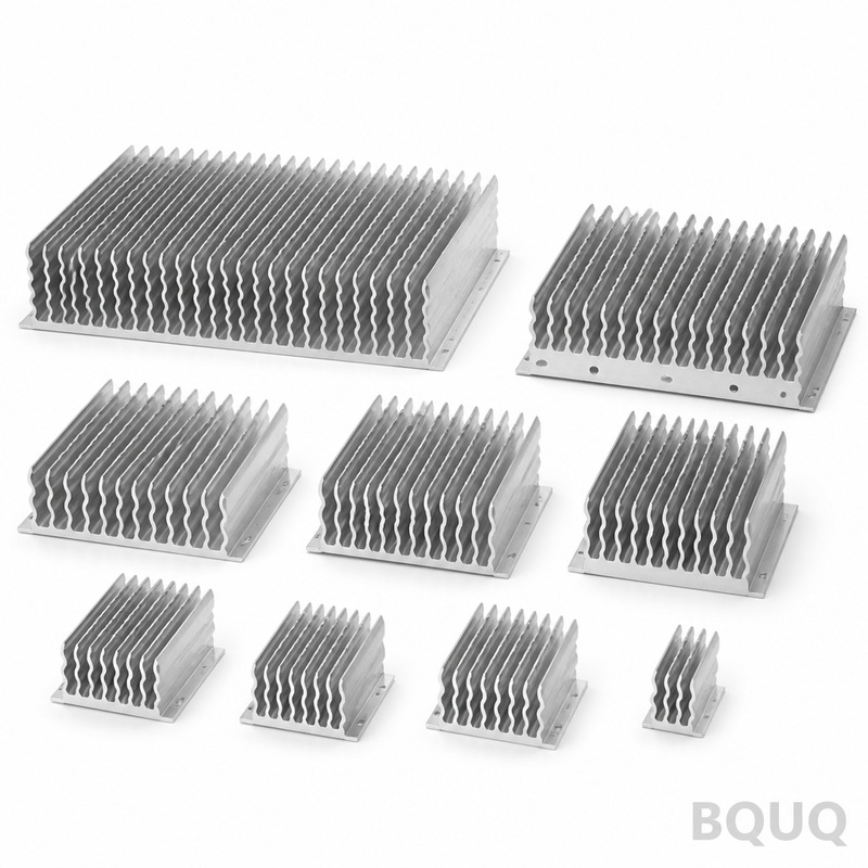
Our CNC machining tolerances for fin geometry are +/- 0.05 mm on thickness and +/- 0.1 mm on spacing. This precision is critical because a 0.2 mm variation in fin spacing can reduce thermal performance by up to 8 percent. The fin efficiency formula, eta = tanh(mL)/(mL) where m equals square root of (2h/(k*t)), shows that fin height should not exceed 15 times the fin thickness for aluminum in natural convection. Exceeding this ratio creates a temperature gradient where the fin tip becomes ineffective.
Base Plate Thickness and Heat Spreading
The base plate must spread heat from a concentrated source (typically a CPU or IGBT package) to the fin array. The minimum base thickness should be 3 to 5 times the diagonal dimension of the heat source divided by 10. For a 20 mm x 20 mm heat source, use a base thickness of 6 mm to 8 mm. Thinner bases create hot spots directly under the source, reducing effective heat transfer area by 15 to 25 percent.
CNC machining allows for tapered base plates, where thickness increases from 5 mm at the edges to 9 mm under the heat source. This reduces material weight by 12 percent while maintaining equivalent thermal spreading resistance. The thermal spreading resistance formula is R = 1/(2*k*sqrt(A_source/pi)) * (1 - sqrt(A_source/A_base))^1.5, which quantifies the penalty of a small source on a large base.
Surface Treatment and Interface Materials
Surface roughness and coating affect both radiation heat transfer and contact resistance. A machined surface finish of Ra 0.8 to 1.6 microns is optimal for thermal interface material (TIM) application. Smoother surfaces (Ra 0.4) do not improve performance with standard TIMs and increase machining cost by 15 percent. Rougher surfaces (Ra 3.2) trap air pockets, increasing interface resistance by 20 to 30 percent.
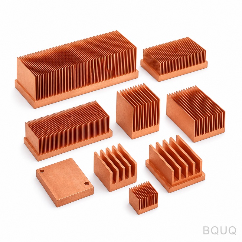
For radiation heat transfer, black anodized surfaces emit at 0.85 to 0.95 emissivity versus 0.10 for raw aluminum. In natural convection where radiation accounts for 20 to 35 percent of total heat dissipation, anodizing can reduce the heat sink temperature by 3 to 6 degrees Celsius. The anodizing cost is $0.30 to $0.80 per square decimeter depending on thickness and color.
Manufacturing Cost and Lead Time Comparison
CNC machining offers design freedom that extrusion cannot match, particularly for complex fin patterns, stepped bases, and integrated mounting features. The following table compares typical costs for a 100 mm x 100 mm x 40 mm heat sink in 6061-T6 aluminum:
| Manufacturing Process | Tooling Cost (USD) | Unit Cost at 100 pcs (USD) | Unit Cost at 1000 pcs (USD) | Lead Time (days) | Maximum Fin Aspect Ratio |
| CNC Machining | 250 | 18.50 | 9.80 | 5 to 7 | 20:1 |
| CNC Machining (5-axis) | 450 | 22.00 | 12.50 | 7 to 10 | 30:1 |
| Aluminum Extrusion | 1800 | 6.20 | 3.40 | 15 to 20 | 10:1 |
| Die Casting | 5500 | 8.50 | 4.20 | 25 to 35 | 6:1 |
| Skiving | 800 | 11.00 | 6.50 | 10 to 12 | 25:1 |
For prototype runs under 50 pieces, CNC machining is always the most economical choice. At volumes above 2000 pieces, extrusion with CNC finishing of the mounting surfaces becomes competitive. Our recommendation is to start with CNC machined samples for thermal validation before committing to high-volume tooling.
Practical Design Recommendations
Specify a base plate thickness of 6 mm minimum for any heat source larger than 15 mm x 15 mm. If the heat flux exceeds 15 W/cm2, consider heat pipe or vapor chamber integration, which CNC machining can accommodate with precision pockets. For natural convection designs, keep total heat sink height under 60 mm to avoid boundary layer interference. For forced convection, orient fins parallel to the airflow direction with a fin density that maintains a pressure drop below 50 Pa.
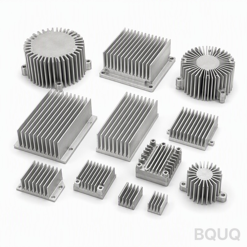
Include mounting hole tolerances of +/- 0.05 mm for the thermal interface surface, and specify flatness of 0.1 mm over the entire base area. This flatness ensures uniform TIM thickness of 50 to 100 microns. A thicker TIM layer increases thermal resistance by approximately 0.1 degree Celsius per 25 microns of extra thickness. Always specify a surface finish of Ra 1.6 or better on the contact face.
FAQ-Style Optimization Tips
Question: How do I calculate the required heat sink size for a 50 W heat source? Answer: For a 50 W source with a maximum junction temperature of 85 degrees Celsius and ambient of 25 degrees Celsius, the total thermal resistance must be below 1.2 degree Celsius per watt. A CNC machined aluminum heat sink with 2000 square centimeters of surface area in natural convection provides approximately 1.0 degree Celsius per watt, which is sufficient with a 15 percent safety margin.
Question: When should I use copper instead of aluminum? Answer: Use copper only when the available footprint is less than 40 percent of the aluminum requirement, or when the heat source is smaller than 10 mm x 10 mm and spreading resistance dominates. Otherwise, the weight and cost penalties outweigh the thermal conductivity benefit.
Question: How much does anodizing affect thermal performance? Answer: Black anodizing improves radiation heat transfer by 5 to 8 percent in natural convection, but the added coating thickness of 25 to 50 microns increases convective resistance by less than 1 percent. The net benefit is positive for natural convection and negligible for forced convection above 3 m/s airflow.
Conclusion
Optimizing heat sink thermal performance requires balancing material thermal conductivity, fin geometry, base plate thickness, and surface treatment against manufacturing cost and lead time. CNC machining provides the tightest tolerances and greatest design flexibility, making it ideal for prototyping and medium-volume production of high-performance heat sinks. The specific parameters provided here—6061-T6 aluminum, 1.2 to 2.0 mm fin thickness, 6 to 8 mm base plate, and black anodized finish—represent the proven sweet spot for most electronics cooling applications.
For your next heat sink project, we provide free design-for-manufacturability reviews and thermal simulation support. Submit your CAD files and receive a detailed quotation within 12 hours, including full tolerance analysis and cost breakdown for your target volume. Contact our engineering team at Email: sc@bquq.com, WhatsApp: +86 13713157787, or visit www.bquq.com to start optimizing your thermal solution today.
Related Articles
- How to Attach a Heat Sink Without Screws: Thermal Adhesive Guide
- Best Copper Heat Sinks for CPU Overclocking in 2025
- Hardware heat sink reconstruction under liquid-cooled penetration of AI server: cold plate, microchannel and two-phase flow
Frequently Asked Questions
What is the best aluminum alloy for CNC machined heat sinks?
6061-T6 and 6063-T5 are the best choices. 6063-T5 offers higher thermal conductivity at 201 W/mK, while 6061-T6 provides better machinability and structural strength at 167 W/mK. For weight-critical applications like aerospace, 6061-T6 with a hard anodized coating (50-100 microns) is recommended.
What fin geometry should I use for natural vs. forced convection?
For natural convection, use fin spacing of 6.5-12 mm and thickness of 1.5-3.0 mm. For forced convection with 2-5 m/s airflow, reduce spacing to 3.0-5.0 mm and thickness to 1.0-2.0 mm. Our CNC tolerances are +/-0.05 mm on thickness and +/-0.1 mm on spacing, as a 0.2 mm variation can reduce performance by up to 8%.
How thick should the base plate be for a 20 mm x 20 mm heat source?
For a 20 mm x 20 mm heat source, use a base thickness of 6-8 mm. This follows the rule of 3-5 times the diagonal dimension divided by 10. Thinner bases create hot spots and can reduce effective heat transfer area by 15-25%.
Why is aluminum preferred over copper for most heat sinks?
Copper (C11000) has higher thermal conductivity at 398 W/mK, but it is 3.3 times heavier and 4-6 times more expensive per kilogram than aluminum. Aluminum alloys like 6061-T6 and 6063-T5 offer 150-210 W/mK, making them the default choice for cost-effective and lightweight applications.


