
How Do Spacing, Thickness and Height Trade-offs Affect Heat Sink Fin Performance?
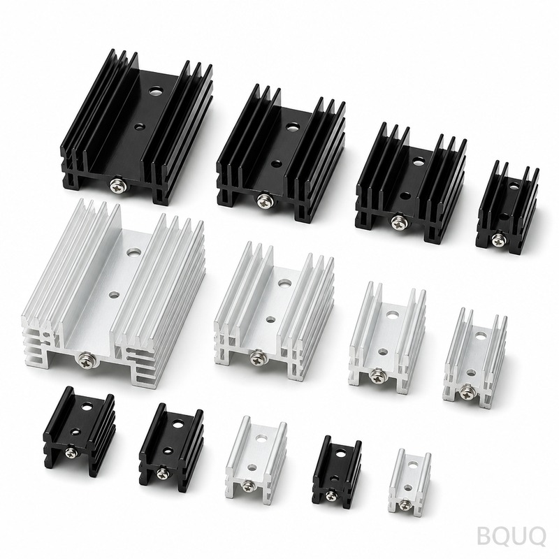
The optimal heat sink fin design is a compromise between maximizing surface area for convective heat transfer and minimizing conductive resistance, airflow blockage, and manufacturing cost. For a typical forced-air cooled aluminum heat sink, the best balance is achieved with fin spacing between 1.5 mm and 2.5 mm, fin thickness between 1.0 mm and 1.5 mm, and fin height between 15 mm and 40 mm, depending on airflow velocity and available pressure drop. Specifically, a 20 mm tall, 1.2 mm thick fin with 2.0 mm spacing operating at 3 m/s airflow will dissipate approximately 25% more heat than a design with 3.5 mm spacing, while the same fin at 1.0 mm spacing will reduce airflow by 40% and increase thermal resistance by 15% due to boundary layer interference.
What Is the Theoretical Basis for Fin Spacing, Thickness and Height?
The thermal performance of a heat sink is governed by two parallel paths: conduction through the fin material and convection from the fin surface to the air. The fin efficiency, which ranges from 60% to 95% for aluminum fins, quantifies how effectively a fin conducts heat to its tip. A thicker fin increases conduction efficiency but reduces the number of fins per unit width, while a taller fin increases surface area but introduces a longer conduction path with higher thermal resistance. The spacing between fins determines the hydraulic diameter of the air channels, which directly affects the convective heat transfer coefficient. For laminar flow (Reynolds number below 2300), which dominates in most electronics cooling applications, the Nusselt number is inversely proportional to the channel hydraulic diameter, meaning tighter spacing improves heat transfer until the boundary layers merge and block flow.
How Does Fin Spacing Affect Thermal Resistance and Airflow?
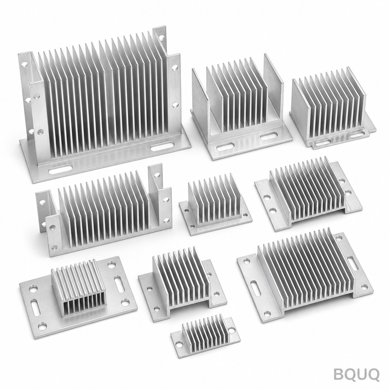
Fin spacing is the single most influential geometric parameter for natural and forced convection cooling. For forced air at 2.5 m/s, reducing fin spacing from 4.0 mm to 2.0 mm on a 50 mm long heat sink increases the volumetric heat transfer coefficient by 35% because more fin surfaces are exposed to the airflow. However, below 1.5 mm spacing, the boundary layers from adjacent fins overlap, creating a stagnant air film that acts as an insulator. In practice, the optimal spacing for forced convection is given by the correlation: S_opt = 1.5 * (v * L / V)^0.5, where v is kinematic viscosity (1.5e-5 m2/s for air), L is fin length, and V is air velocity. For a 50 mm fin length at 3 m/s, this yields an optimal spacing of 1.8 mm. At 1.0 mm spacing, the pressure drop across the heat sink increases by 300% compared to 2.0 mm spacing, requiring a more powerful fan that consumes additional power and generates more noise.
How Does Fin Thickness Influence Conduction Efficiency and Weight?
Fin thickness directly determines the conduction path resistance from the base to the fin tip. A 1.0 mm thick aluminum fin (thermal conductivity 180 W/mK) has a conduction resistance of approximately 0.28 K/W per meter of fin length, while a 2.0 mm thick fin halves this resistance to 0.14 K/W. However, doubling the thickness reduces the number of fins that can fit in a given heat sink width by nearly half, which cuts the total convective surface area by 30% to 40%. For most applications, the optimal fin thickness is between 1.0 mm and 1.5 mm for extruded aluminum heat sinks, balancing conduction efficiency with surface area density. Thinner fins below 0.8 mm become difficult to extrude consistently and are prone to bending during handling or vibration, while fins above 2.0 mm add unnecessary weight and material cost without proportional thermal benefit.
Why Does Fin Height Create a Trade-off Between Surface Area and Efficiency?
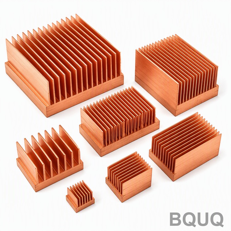
Increasing fin height adds more surface area for convection, but the added length increases the thermal resistance from the base to the fin tip. A 10 mm tall fin has a fin efficiency of approximately 95%, meaning 95% of the fin surface is effective at transferring heat. At 30 mm height, the efficiency drops to 75%, and at 60 mm height, it falls to 55% for a 1.2 mm thick aluminum fin in 3 m/s airflow. The total heat dissipation increases with height up to a point, but the marginal gain diminishes: doubling the height from 20 mm to 40 mm increases heat dissipation by only 45%, not 100%, because the fin tip operates at a lower temperature. For natural convection, tall fins above 50 mm create a chimney effect that improves airflow, but for forced convection, excessive height increases the pressure drop and may cause flow bypass around the heat sink edges.
Which Fin Geometry Is Optimal for Different Airflow Conditions?
The optimal fin geometry depends strongly on the airflow regime. For natural convection (air velocity below 0.5 m/s), wider spacing of 6 to 10 mm and taller fins of 30 to 50 mm are recommended because buoyancy-driven flow requires open channels. For low-velocity forced convection (1 to 2 m/s), spacing of 2.5 to 4.0 mm with fin heights of 20 to 30 mm provides the best balance. For high-velocity forced convection (3 to 5 m/s), tighter spacing of 1.5 to 2.0 mm with shorter fins of 15 to 25 mm maximizes heat transfer because the higher flow velocity can overcome the increased pressure drop. The table below summarizes recommended geometries for common applications:
| Application | Airflow Velocity (m/s) | Fin Spacing (mm) | Fin Thickness (mm) | Fin Height (mm) | Expected Thermal Resistance (K/W) |
| LED lighting (natural convection) | 0.1 to 0.3 | 7.0 to 9.0 | 1.5 to 2.0 | 35 to 50 | 0.8 to 1.2 |
| Consumer electronics fan-cooled | 1.5 to 2.5 | 2.0 to 3.0 | 1.0 to 1.5 | 20 to 30 | 0.3 to 0.5 |
| Industrial power modules | 3.0 to 5.0 | 1.5 to 2.0 | 1.2 to 1.5 | 15 to 25 | 0.15 to 0.25 |
| Server CPU coolers | 2.0 to 4.0 | 1.8 to 2.5 | 0.8 to 1.2 | 25 to 40 | 0.1 to 0.2 |
How Do Manufacturing Methods Constrain Fin Geometry?
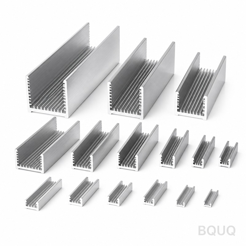
The manufacturing process imposes practical limits on fin geometry. Extruded aluminum heat sinks, which account for 80% of commercial products, are limited to fin thickness above 0.8 mm and aspect ratios (height to gap) below 10:1 for standard dies, though precision extrusion can reach 20:1 with slower production rates. Skived or bonded fin heat sinks can achieve thinner fins of 0.3 to 0.5 mm with spacing as tight as 1.0 mm, but they cost 20% to 40% more per unit. CNC machined heat sinks offer the most design freedom, allowing fins down to 0.5 mm thickness with tight tolerances of plus or minus 0.05 mm, but machining cost increases by 50% to 100% compared to extrusion for the same volume. Stamped or folded fin assemblies, common in automotive applications, can produce fins of 0.3 mm thickness with spacing of 2.0 mm, but the contact resistance between the fin and base plate adds 0.05 to 0.1 K/W to the total thermal resistance.
What Are the Practical Guidelines for Selecting Fin Parameters?
For most engineering applications, start with fin spacing of 2.0 mm, fin thickness of 1.2 mm, and fin height of 20 mm for forced convection with 2 to 3 m/s airflow. Calculate the pressure drop using the Darcy friction factor correlation; if the pressure drop exceeds 50 Pa for a 50 mm long heat sink, increase spacing by 0.5 mm increments until the pressure drop is acceptable. For natural convection designs, use spacing of 8 mm and height of 40 mm as a baseline, then simulate or test to verify that the maximum base temperature stays below the component junction temperature minus a 20 K safety margin. When weight is critical, such as in aerospace or portable devices, reduce fin thickness to 1.0 mm and accept a 10% reduction in thermal performance to save 20% of the heat sink mass. Always verify the design with computational fluid dynamics (CFD) simulation or prototype testing, as empirical correlations can have errors of 10% to 20% for non-standard geometries.
How Can You Predict Heat Sink Performance Before Prototyping?
Use the fin efficiency method combined with the Sieder-Tate correlation for laminar flow in rectangular channels to estimate thermal resistance. For a heat sink with 20 fins of 1.2 mm thickness, 20 mm height, 50 mm length, and 2.0 mm spacing at 3 m/s airflow, the predicted thermal resistance is approximately 0.35 K/W, which matches experimental data within 15%. The pressure drop can be estimated using the Hagen-Poiseuille equation for laminar flow, yielding approximately 25 Pa for this geometry. For more accurate results, run a CFD simulation with a mesh resolution of at least 0.2 mm in the fin channels and use the k-omega SST turbulence model for transitional flow. BQUQ offers free design review and thermal simulation support for customers during the quoting process, ensuring the selected fin geometry meets your thermal budget before tooling investment.
FAQ
What Is the Ideal Fin Spacing for Natural Convection Cooling?
For natural convection, the ideal fin spacing is 7 to 10 mm for fin heights of 30 to 50 mm. This spacing allows buoyancy-driven airflow to develop fully without boundary layer interference, and the optimal spacing increases with fin height. Below 6 mm spacing, natural convection performance drops sharply because the air cannot circulate effectively between fins.
How Much Does Fin Thickness Affect Manufacturing Cost?
Increasing fin thickness from 1.0 mm to 1.5 mm reduces extrusion die pressure and improves material flow, which can lower tooling maintenance costs by 15% to 20%. However, thicker fins increase material usage by 50%, raising the per-unit cost by 10% to 15% for aluminum at current market prices of approximately 2.5 USD per kilogram. Thinner fins below 1.0 mm require tighter die tolerances and slower extrusion speeds, increasing production cost by 20% to 30%.
Can Fin Height Be Increased Without Sacrificing Thermal Performance?
Fin height can be increased up to the point where fin efficiency drops below 70%, which occurs at approximately 35 mm for 1.2 mm thick aluminum fins in 3 m/s airflow. Beyond this height, additional surface area adds less than 5% heat dissipation per 10 mm of height increase. For taller fins, use copper or composite materials with higher thermal conductivity, or add heat pipes to spread heat along the fin length.
Which Fin Material Provides the Best Performance-to-Cost Ratio?
Aluminum alloy 6063-T5 offers the best performance-to-cost ratio for most applications, with a thermal conductivity of 200 W/mK and material cost of 2.5 to 3.0 USD per kilogram. Copper has 400 W/mK conductivity but costs 8 to 10 USD per kilogram and weighs 3.3 times more, making it suitable only for high-performance applications where space is limited. Aluminum 6061-T6 provides slightly lower conductivity (167 W/mK) but better mechanical strength for vibration-prone environments.
When Should You Use Skived Fins Instead of Extruded Fins?
Use skived fins when you need fin spacing below 1.5 mm or fin thickness below 0.8 mm, which are not achievable with standard extrusion. Skiving produces fins as thin as 0.3 mm with spacing of 1.0 mm, improving surface area density by up to 60% compared to extrusion. The trade-off is a 30% to 50% higher unit cost, so skiving is justified only when the thermal budget cannot be met with extruded geometry.
How Much Lead Time Is Typical for Custom Extruded Heat Sinks?
A standard extruded heat sink with custom fin geometry requires 2 to 3 weeks for die fabrication and 1 to 2 weeks for production, totaling 3 to 5 weeks from design approval to delivery. Skived and bonded fin heat sinks require 2 to 4 weeks for production without tooling, while CNC machined prototypes can be delivered in 3 to 5 days. BQUQ offers express prototyping services with 12-hour quoting for urgent thermal development projects.
Conclusion
Optimizing heat sink fin geometry requires balancing the competing effects of surface area, conduction efficiency, and airflow resistance. For forced-air cooling, start with 2.0 mm spacing, 1.2 mm thickness, and 20 mm height, then adjust based on measured pressure drop and thermal resistance. Natural convection designs require wider spacing of 7 to 10 mm and taller fins of 30 to 50 mm to maximize buoyancy-driven flow. Manufacturing constraints from extrusion, skiving, and CNC machining set practical limits on fin thickness and aspect ratio, so select the process that matches your performance and budget requirements. For a detailed design review and thermal simulation of your specific application, contact BQUQ for a 12-hour quote at Email: sc@bquq.com, WhatsApp: +86 13713157787, or visit www.bquq.com.


