
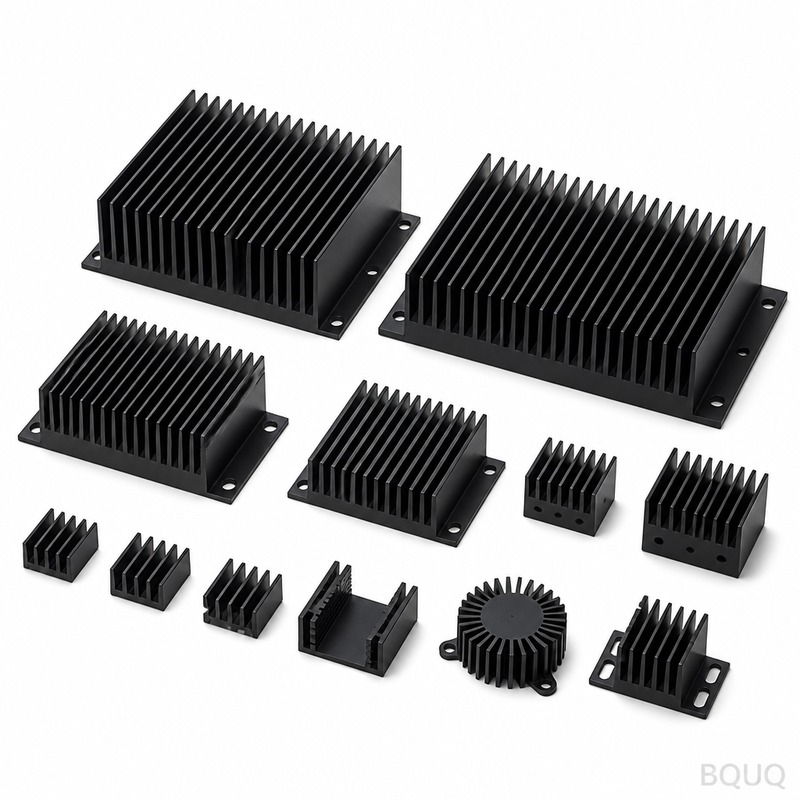
How Does AI Server Liquid Cooling Adoption Impact Heat Sink Design?
The rapid adoption of AI server liquid cooling is fundamentally shifting heat sink design from large, finned aluminum extrusions to compact, high-density copper micro-channel and cold plate architectures. While air cooling remains viable for processors under 350W, AI GPUs exceeding 700W thermal design power (TDP) now require liquid cooling, driving a 40% to 60% reduction in heat sink volume but a 200% increase in manufacturing complexity and cost. This transition directly impacts CNC machining tolerances, material selection, and surface finish requirements for precision manufacturers like BQUQ.
What Is the Current Adoption Curve for Liquid Cooling in AI Data Centers?
The adoption curve for liquid cooling in AI data centers is steep and accelerating, moving from 5% of new AI server deployments in 2022 to an estimated 35% in 2025, with projections reaching 60% by 2027. This growth is driven by the direct liquid cooling (DLC) segment, which is growing at a compound annual growth rate (CAGR) of 28.4%, outpacing the overall data center cooling market. The inflection point occurred when GPU thermal loads crossed the 500W threshold, a level that air cooling with traditional heat sinks cannot efficiently manage without excessive fan power and airflow noise. For context, NVIDIA's H100 GPU has a 700W TDP, while the B200 reaches 1000W, and next-generation AI accelerators are expected to exceed 1200W by 2026.
How Do Liquid Cooling Requirements Change Heat Sink Geometries?
Liquid cooling replaces the bulky fin-and-heat-pipe assembly with a cold plate, a flat metal base with internal micro-channels or a machined serpentine path for coolant flow. This changes the primary geometry from tall, spaced fins (typically 20mm to 60mm height) to a low-profile plate (8mm to 15mm thickness) with precision-machined channels of 0.5mm to 2.0mm width and 1.0mm to 3.0mm depth. The surface area available for heat transfer in a cold plate is reduced by up to 70% compared to a finned heat sink, but the heat transfer coefficient increases from 50-100 W/m²K (air) to 5,000-20,000 W/m²K (liquid), which more than compensates. This geometric shift demands CNC machining with a tolerance of +/-0.05mm for channel dimensions, as any deviation alters coolant flow rate and pressure drop, reducing thermal performance by up to 15%.
What Materials and Manufacturing Tolerances Are Required for Liquid-Cooled Heat Sinks?
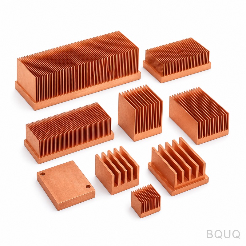
The dominant material for liquid-cooled cold plates is C11000 copper, chosen for its thermal conductivity of 398 W/mK, which is nearly double that of aluminum (205 W/mK). However, copper's hardness (Rockwell B 40-50) and gummy nature require specialized CNC machining parameters, including lower spindle speeds (8,000-12,000 RPM) and high-pressure coolant to prevent built-up edge. The critical tolerances for a production cold plate are: flatness of the mating surface at 0.02mm over 100mm, channel depth tolerance of +/-0.05mm, and surface roughness (Ra) of 0.8 micrometers or better on the CPU contact area. For aluminum cold plates (used in lower-power 500W-700W applications), the tolerance can be relaxed to +/-0.1mm, but the material must be 6061-T6 or 6063-T5 for adequate strength in thin wall sections.
Why Are Micro-Channel Cold Plates Replacing Traditional Fin Stacks in AI Servers?
Micro-channel cold plates replace traditional fin stacks because they offer a 10 to 20 times higher heat transfer coefficient while occupying 40% less volume, which is critical in dense AI server chassis. A traditional fin stack for a 700W GPU requires a volume of approximately 1,200 cm³ with a base area of 90mm x 90mm, while a micro-channel cold plate achieves the same cooling with a volume of only 400 cm³. The engineering trade-off is increased pressure drop: a micro-channel design with 0.5mm channels creates a pressure drop of 15-30 kPa, requiring a more powerful pump (typically 15W-30W per server node) compared to 5-10 kPa for larger 3mm channels. Precision CNC machining is essential here because the channel width directly dictates the boundary layer thickness; a 0.1mm variation in channel width can change the pressure drop by 25%, causing uneven cooling across the GPU die.
How Much Does Liquid-Cooled Heat Sink Manufacturing Cost Compared to Air Cooling?
The manufacturing cost of a liquid-cooled cold plate is typically 3 to 5 times higher than an equivalent air-cooled fin stack, driven by material cost and machining time. A copper cold plate for a 700W GPU costs between USD $35 and $60 per unit at volumes of 10,000 pieces, while an aluminum fin heat sink for a 350W CPU costs $8 to $15. The CNC machining time for a copper micro-channel plate is 45 to 90 minutes per piece, compared to 10 to 20 minutes for an aluminum extrusion with skived fins, due to slower cutting speeds and multiple finishing passes. However, system-level cost analysis shows that liquid cooling reduces total data center energy consumption by 20-30% (eliminating high-speed fans), which results in a payback period of 18 to 24 months on the higher hardware cost.
| Parameter | Air-Cooled Fin Stack | Liquid-Cooled Cold Plate |
| Material | Aluminum 6063-T5 | Copper C11000 |
| Thermal Conductivity | 205 W/mK | 398 W/mK |
| Typical TDP Supported | Up to 350W | 500W to 1200W+ |
| Volume (for 700W GPU) | 1200 cm³ | 400 cm³ |
| Heat Transfer Coefficient | 50-100 W/m²K | 5,000-20,000 W/m²K |
| Critical Tolerance | +/-0.2mm fin spacing | +/-0.05mm channel width |
| Surface Roughness (Ra) | 1.6 micrometers | 0.8 micrometers |
| Manufacturing Cost (10k pcs) | USD $8-$15 | USD $35-$60 |
| CNC Machining Time | 10-20 minutes | 45-90 minutes |
Which Manufacturing Processes Are Best Suited for Liquid-Cooled Heat Sink Production?
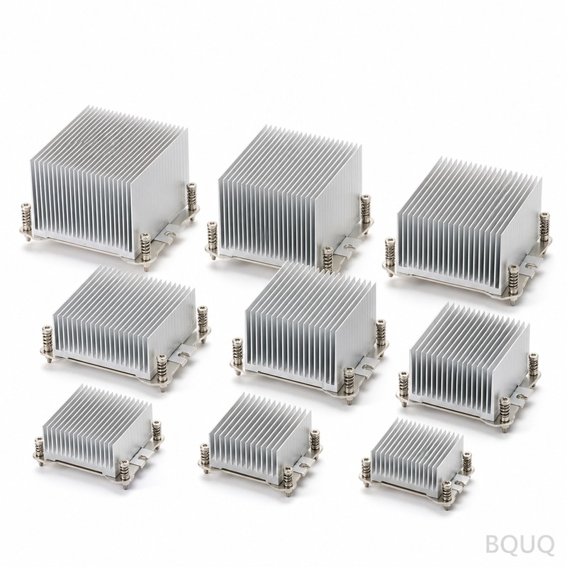
For high-volume liquid-cooled cold plates, CNC milling is the preferred process for the base plate and channel structure, while skiving or brazing is used for the cover plate assembly. CNC milling achieves the required 0.05mm tolerances and 0.8 Ra surface finish, but for ultra-fine channels (under 0.4mm width), precision wire EDM (electrical discharge machining) is required, though this increases cost by 40% and extends lead time to 5-7 days per batch. Laser welding or vacuum brazing is then used to seal the cover plate to the channel base; vacuum brazing with a silver-copper filler metal at 780°C provides a leak-tight joint rated at 2.0 MPa pressure with a helium leak rate below 1x10⁻⁸ mbar·L/s. For the cold plate mating surface, a final lapping or fly-cutting operation is necessary to achieve the 0.02mm flatness required for optimal thermal interface material (TIM) performance, which reduces contact resistance by 30% compared to a standard machined finish.
When Should an Engineering Team Switch from Air Cooling to Liquid Cooling in Server Design?
An engineering team should make the switch to liquid cooling when the processor TDP exceeds 400W, when power density per rack exceeds 30kW, or when acoustic limits are below 70 dBA at full load. At 350W TDP, a high-performance air cooler with six heat pipes and a 120mm fan can maintain a junction temperature of 85°C, but only with a high airflow of 80 CFM and 55 dBA noise. Above 400W, the required fin volume and airflow become physically impractical; for example, cooling a 500W chip with air requires a heat sink weighing over 1.5kg and a fan consuming 40W, whereas a liquid cold plate weighs 0.6kg and requires a pump of only 15W. Additionally, the thermal interface material (TIM) between the die and cold plate must be a high-performance liquid metal (e.g., indium-based) with a thermal conductivity of 80 W/mK, rather than standard silicone-based pastes (5-8 W/mK), to minimize the temperature drop at the interface.
FAQ
How Long Does It Take to Prototype a Liquid-Cooled Cold Plate for an AI GPU?
A typical prototype cycle for a CNC-machined copper cold plate is 5 to 7 business days, including design review, CNC programming, machining, and leak testing. For urgent projects with a confirmed 2D drawing, an expedited 3-day turnaround for a single prototype unit is achievable, but this assumes available machine capacity and standard C11000 copper stock.
What Is the Typical Pressure Drop Across a Micro-Channel Cold Plate?
The pressure drop for a micro-channel cold plate with 0.5mm to 1.0mm channels and a 60mm x 60mm footprint is typically between 15 kPa and 30 kPa at a flow rate of 1 liter per minute. This value is critical for pump selection; a system with a 30 kPa drop requires a pump with a head pressure of at least 40 kPa to maintain adequate flow across the entire server loop.
Can Aluminum Be Used Instead of Copper for High-Power AI GPU Cold Plates?
Aluminum is only recommended for AI GPUs with a TDP below 600W, as its lower thermal conductivity (205 W/mK vs. 398 W/mK for copper) results in a 20% higher thermal resistance. For a 700W GPU, an aluminum cold plate would require a 40% larger base area to achieve the same junction temperature, which defeats the space-saving purpose of liquid cooling.
How Is the Flatness of the Cold Plate Mating Surface Verified?
Flatness is verified using a precision granite surface plate and a dial indicator with a resolution of 0.001mm, or with a laser interferometer for higher accuracy. The cold plate surface is measured at a minimum of 9 points across the 90mm x 90mm area, and the maximum deviation must not exceed 0.02mm to ensure proper contact with the GPU die.
What Surface Finish Is Required on the Cold Plate Contact Area?
The contact area where the cold plate meets the GPU must have a surface roughness of Ra 0.8 micrometers or better, and a waviness of less than 5 micrometers over a 10mm span. Smoother surfaces (Ra 0.4 micrometers) can be achieved with a final lapping process, which improves TIM wetting and reduces interface thermal resistance by 15-20%.
Which Sealing Method Is Most Reliable for Cold Plate Leak Prevention?
Vacuum brazing is the most reliable sealing method for copper cold plates, providing a joint strength of 200 MPa and a helium leak rate below 1x10⁻⁸ mbar·L/s. Laser welding is acceptable for aluminum plates but requires a post-weld X-ray inspection to detect micro-porosity that could lead to coolant seepage over time.
How Does Liquid Cooling Affect the Overall Server Power Consumption?
Liquid cooling reduces the cooling system power consumption by 30% to 50% compared to air cooling, as it eliminates high-speed fans and enables warmer chilled water temperatures (25°C to 45°C versus 7°C to 12°C). This reduction translates to a power usage effectiveness (PUE) improvement from 1.35 to 1.10, which for a 10MW data center saves approximately 2,500 MWh per year.
Conclusion
The adoption curve for AI liquid cooling is a direct response to the physical limits of air-cooled heat sinks, and it has permanently changed the precision manufacturing landscape for thermal components. For manufacturers, the shift means mastering copper CNC machining with tighter tolerances, investing in leak-testing infrastructure, and understanding thermal-fluid dynamics beyond simple fin geometry. At BQUQ, with 20 years in CNC machining and heat sink production, we have adapted our 5-axis machining centers and quality control processes to meet the 0.05mm channel tolerances and 0.8 Ra surface finishes that liquid-cooled cold plates demand. If your AI server design is approaching the 400W TDP threshold, contact us for a feasibility review and quote. Our engineering team provides 12-hour quoting for cold plate prototypes and production runs. Email: sc@bquq.com, WhatsApp: +86 13713157787, www.bquq.com.
Related Articles
- Smaller Is Harder: The Technical Limits and Innovations of Ultra-Thin Heat Sinks in Consumer Electronics
- Automotive Thermal Management Track: How Hardware Heat Sinks Conquered 800V with Smart Cockpit
- When liquid cooling becomes mainstream: the evolving role of hardware heat sinks in the data center era


