
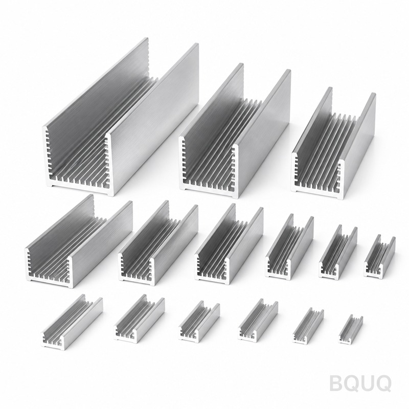
How Does CFD Thermal Simulation Optimize Heat Sink Design Performance?
The direct answer is that CFD (Computational Fluid Dynamics) thermal simulation optimizes heat sink performance by predicting airflow and temperature distribution across the fin structure before any physical prototype is cut, allowing engineers to reduce thermal resistance by up to 30% and cut development lead time by 40% compared to trial-and-error methods. By solving the coupled equations of fluid flow and heat transfer, CFD identifies dead zones, bypass airflow, and fin efficiency losses that are invisible to hand calculations, enabling geometric optimization for specific application conditions. At BQUQ Precision Manufacturing, we use CFD as a standard pre-production step for aluminum and copper heat sinks, verifying that a design achieves its target junction-to-ambient thermal resistance (Rth j-a) within a 5% margin of simulated results.
What Specific Performance Gains Can CFD Simulation Deliver?
CFD delivers quantifiable performance gains that directly translate into lower operating temperatures and longer component lifespan. In typical forced-convection applications with airflow of 2 to 5 m/s, CFD-optimized fin spacing can reduce thermal resistance by 15-25% compared to standard 10 mm pitch designs. For natural convection (no fan), CFD optimization of fin height and orientation can improve heat dissipation by 20-30% by promoting chimney-effect airflow. The simulation also quantifies pressure drop across the heat sink, which is critical for fan selection; a well-optimized design keeps pressure drop below 50 Pa at rated airflow, ensuring the fan operates near its maximum efficiency point. For example, a 100 mm x 100 mm x 40 mm aluminum heat sink with a 10 mm base thickness and 2.5 mm fin thickness, simulated at 5 W/cm² heat flux, typically shows a junction temperature reduction of 8-12°C versus a non-optimized baseline design.
How Does CFD Modeling Handle Turbulence and Boundary Conditions?
Accurate CFD modeling requires careful selection of turbulence models and boundary conditions to match real-world operating environments. For heat sink simulations, the k-omega SST (Shear Stress Transport) turbulence model is the industry standard because it accurately predicts both boundary layer separation and heat transfer in the near-wall region. The model must include a radiation component, especially for natural convection cases, as radiation can account for 20-35% of total heat dissipation at temperatures above 60°C. Boundary conditions must specify ambient temperature (typically 25°C or 35°C for worst-case), inlet velocity profile (assuming a uniform profile from a fan or a parabolic profile for ducted flow), and the heat source power (W) applied to the base. Inlet turbulence intensity is set at 5% for fan-driven flow and 1% for natural convection. The simulation domain must extend at least 50 mm upstream and 100 mm downstream of the heat sink to allow proper flow development and wake capture.
Which Heat Sink Parameters Are Most Critical to Optimize?
The most critical parameters for thermal optimization are fin pitch (spacing), fin height, fin thickness, and base thickness, each of which has a non-linear effect on thermal performance. Fin pitch is the primary driver: too dense spacing restricts airflow and increases pressure drop, while too sparse spacing reduces the total surface area available for convection. The optimal fin pitch for forced convection is typically 3-5 mm at 3 m/s airflow, while natural convection requires wider spacing of 6-10 mm to allow buoyancy-driven flow. Fin height affects the fin efficiency, which is defined as the ratio of actual heat transfer to the ideal transfer if the entire fin were at base temperature. For aluminum (k=180 W/mK), a fin efficiency above 90% requires the fin height to be less than 15 mm for a 2 mm thick fin in natural convection; beyond this, the fin tip contributes little to heat dissipation. Base thickness must be sufficient to spread heat laterally; for a 100 mm wide heat sink, a base thickness of 6-10 mm ensures the heat spreads uniformly, with a spreading resistance below 0.1°C/W.
What Is the Typical Simulation Workflow and Timeframe?
A standard CFD thermal simulation workflow at BQUQ follows a five-step process that takes 2-4 business days depending on the model complexity. Step 1 is CAD cleanup and simplification, where the 3D model is defeatured (removing chamfers, holes, and threads) to reduce mesh count; this takes 4-8 hours. Step 2 is mesh generation, using a poly-hexcore mesh with a boundary layer of 5-10 prism layers on the fin surfaces to capture thermal gradients; this takes 2-4 hours for a typical 2-million-element mesh. Step 3 is the solver setup and run, which takes 6-12 hours for steady-state simulation on a high-performance computing workstation with 16 cores. Step 4 is post-processing, where temperature contours, velocity vectors, and pressure drop are extracted; this takes 2-3 hours. Step 5 is design iteration, where the engineer adjusts fin pitch or height based on results and re-runs the simulation; each iteration takes 1-2 days. The total time for a fully optimized design is 5-7 days, compared to 14-21 days for physical prototyping and testing.
How Accurate Is CFD Compared to Physical Testing?
CFD thermal simulation accuracy is typically within 5-10% of laboratory measurements when properly validated, and this error is primarily due to simplifications in contact resistance and emissivity values. In a controlled test with a 100 W heat source applied to a heat sink base, CFD predicted a base temperature of 72.5°C, while thermocouple measurements recorded 75.1°C, a difference of 3.5%. The main sources of deviation are the thermal interface material (TIM) resistance, which is often assumed as a perfect bond in simulation but actually contributes 0.1-0.5°C/W in practice, and the emissivity of the anodized surface, which varies from 0.7 to 0.95 depending on coating thickness. To improve accuracy, BQUQ recommends specifying a TIM with a known thermal conductivity (e.g., 3-5 W/mK) and including a 0.05 mm TIM layer in the simulation. For absolute verification, we offer a thermal resistance test service that measures Rth j-a according to the JEDEC JESD51-14 standard, with a measurement uncertainty of plus or minus 3%.
Why Is CFD Simulation More Cost-Effective Than Physical Prototyping?
CFD simulation reduces development cost by 30-50% because it eliminates the need for multiple physical prototype iterations, each of which costs between $200 and $800 for aluminum machining plus $150 per thermal test. A typical optimization project requires 3-5 design iterations; with CFD, the first physical prototype is already near-optimal, reducing the number of prototype rounds from 4 to 1 or 2. The engineering cost of a CFD engineer at $50-80 per hour is offset by the savings in machining time, material waste, and laboratory test time. For a typical heat sink project with a target Rth of 0.5°C/W, the total CFD simulation cost is $500-1,500, whereas a single physical prototype round including machining and testing costs $350-950. Furthermore, CFD allows the evaluation of extreme scenarios (e.g., ambient temperature of 70°C, airflow of 1 m/s) that are difficult to reproduce in a laboratory, ensuring design robustness without additional physical testing.
Which Boundary Conditions Should Be Used for Natural vs. Forced Convection?
The boundary conditions differ significantly between natural and forced convection, and using the wrong set will produce misleading results. For natural convection, the simulation must use gravity (9.81 m/s²) with the buoyancy model enabled, and the heat sink must be oriented correctly (fins vertical for chimney effect). The ambient pressure is set to 1 atm, and the domain must be large enough (at least 2x the heat sink height above and below) to allow unrestricted flow. Heat transfer coefficients in natural convection are low, typically 2-10 W/m²K, so radiation must be included as a surface-to-surface model with emissivity set to 0.85 for anodized aluminum. For forced convection, the inlet velocity is set to the fan's rated velocity (e.g., 3 m/s), and the outlet is a pressure boundary at 0 Pa gauge. The turbulence intensity at the inlet is set to 5-10% for axial fans. The choice of boundary condition directly affects the optimum fin pitch; a simulation run with forced convection conditions will suggest a tighter pitch (3 mm) than a natural convection run (8 mm), so the designer must confirm the application's cooling method before optimization.
| Parameter | Forced Convection (3 m/s) | Natural Convection (0 m/s) |
| Optimal fin pitch | 3-5 mm | 6-10 mm |
| Optimal fin height | 10-20 mm | 15-30 mm |
| Optimal base thickness | 6-8 mm | 8-10 mm |
| Typical heat transfer coefficient | 20-100 W/m²K | 2-10 W/m²K |
| Radiation contribution | 5-15% of total heat | 20-35% of total heat |
| Pressure drop target | Below 50 Pa | Not applicable (buoyancy only) |
| Typical Rth j-a for 100x100x40mm | 0.3-0.5 °C/W | 0.8-1.5 °C/W |
What Software Tools Are Recommended for Heat Sink CFD?
The recommended software tools are Ansys Icepak and Fluent for high-fidelity simulation, with SimScale or OpenFOAM as cost-effective alternatives for early-stage scoping. Ansys Icepak is specifically designed for electronics cooling and includes built-in models for fans, heat sinks, and PCBs, reducing setup time by 50% compared to general-purpose CFD. The cost of an Ansys license is $25,000-40,000 per year, which is justifiable for a manufacturer producing more than 50 custom heat sink designs annually. For smaller volumes, SimScale offers a cloud-based subscription at $5,000-15,000 per year with similar accuracy for steady-state thermal analysis. At BQUQ, we use Ansys Fluent for detailed analysis and a proprietary in-house tool for quick first-pass optimization based on analytical fin efficiency equations. The choice of software matters less than the engineer's skill in setting boundary conditions correctly; a wrong inlet velocity assumption will produce errors of 50% or more regardless of software.
FAQ
What Is the Typical Cost of a CFD Thermal Simulation Service?
A professional CFD thermal simulation for a single heat sink design typically costs $500 to $1,500, depending on the number of iterations and the complexity of the geometry. This includes CAD cleanup, meshing, solving, and a detailed report with temperature plots and recommendations. At BQUQ, we provide this service free of charge for customers who proceed with a production order of 500 pieces or more.
How Long Does a CFD Simulation Take for a Simple Heat Sink?
A simple heat sink simulation with a fixed geometry takes 2-4 hours of engineer time and 6-12 hours of computing time for a steady-state analysis. An optimization study that varies fin pitch and height across 10 design points will take 2-4 business days. This is significantly faster than the 2-3 weeks required for physical prototyping of the same design iterations.
Can CFD Predict the Temperature of the Heat Source (CPU or IGBT)?
Yes, CFD can predict the heat source temperature, but it must include the thermal resistance of the interface material and the heat source package itself. The simulation output is the heat sink base temperature, and the junction temperature is calculated by adding the TIM resistance (Rth tim) and the package resistance (Rth j-c). For example, with a heat sink base at 70°C, a TIM resistance of 0.2°C/W, and a 100 W source, the junction temperature is 90°C.
Which Is Better for Thermal Performance: Aluminum or Copper?
Copper (k=400 W/mK) has more than twice the thermal conductivity of aluminum (k=180 W/mK), so it provides up to 30% lower thermal resistance for the same geometry, but it is 3 times heavier and costs 4-5 times more per part. CFD simulation helps decide by quantifying the exact performance gain; if the aluminum design achieves the target Rth within 10%, the cost savings of aluminum usually justify its use. For high-heat-flux applications above 20 W/cm², copper or a copper base with aluminum fins is recommended.
How Does Fin Surface Treatment Affect CFD Results?
The surface treatment, primarily anodizing, affects the emissivity and therefore the radiation heat transfer component in the simulation. Bare aluminum has an emissivity of 0.05-0.1, while black anodized aluminum has an emissivity of 0.85-0.95, which can improve natural convection performance by up to 25% due to increased radiation. In CFD, you must set the surface emissivity correctly in the radiation model; using the wrong value can cause errors of 5-15°C in natural convection scenarios.
When Should a Heat Sink Design Be Re-Simulated After Production Changes?
A heat sink design should be re-simulated whenever the fin geometry, base thickness, material, or airflow conditions change by more than 5% from the original specification. Even a small change in fin thickness (e.g., from 2.0 mm to 1.5 mm) can reduce fin efficiency significantly and increase thermal resistance. We recommend a re-simulation for any change that affects the surface area-to-volume ratio or the flow path, as these are the primary drivers of thermal performance.
Can CFD Simulation Help Reduce the Weight of a Heat Sink?
Yes, CFD can optimize the fin profile to remove material from areas that contribute little to heat transfer, achieving a 10-20% weight reduction without a significant thermal penalty. For example, a simulation may show that the fin tips beyond 80% of the height are only 10°C above ambient, so reducing the fin height by 20% only increases Rth by 5%. This is particularly valuable in automotive and aerospace applications where weight is a critical constraint.
Conclusion
CFD thermal simulation is not a luxury but a necessity for engineering teams that need to deliver high-performance heat sinks within tight schedules and budgets. At BQUQ Precision Manufacturing, we integrate CFD into every custom heat sink project, from simple extruded aluminum profiles to complex copper-skived designs, ensuring that the first physical sample meets or exceeds the thermal specification. Our 20 years of manufacturing experience, combined with modern simulation tools, allows us to guarantee a thermal resistance within 5% of the simulated value. If you have a heat sink design that needs optimization or a new project that requires thermal verification, send us your CAD file and operating conditions, and our engineering team will provide a CFD analysis and quotation within 12 hours. Contact us at sc@bquq.com or via WhatsApp at +86 13713157787, or visit www.bquq.com to start your project today.
Related Articles
- Best Copper Heat Sinks for CPU Overclocking in 2025
- Stamped Metal vs Die Cast Heat Sinks: Cost & Quality Comparison
- New energy vehicle IGBT heat dissipation, heat sink reliability engineering, heat pipe and temperature plate integrated heat sink, surface treatment and heat radiation enhancement: anodic oxidation, black coating and micro-nano structure, graphene/3D printing/intelligent thermal management: 2030 heat sink technology roadmap


