
How Does Heat Sink Base Thickness Affect Heat Spreading Performance?
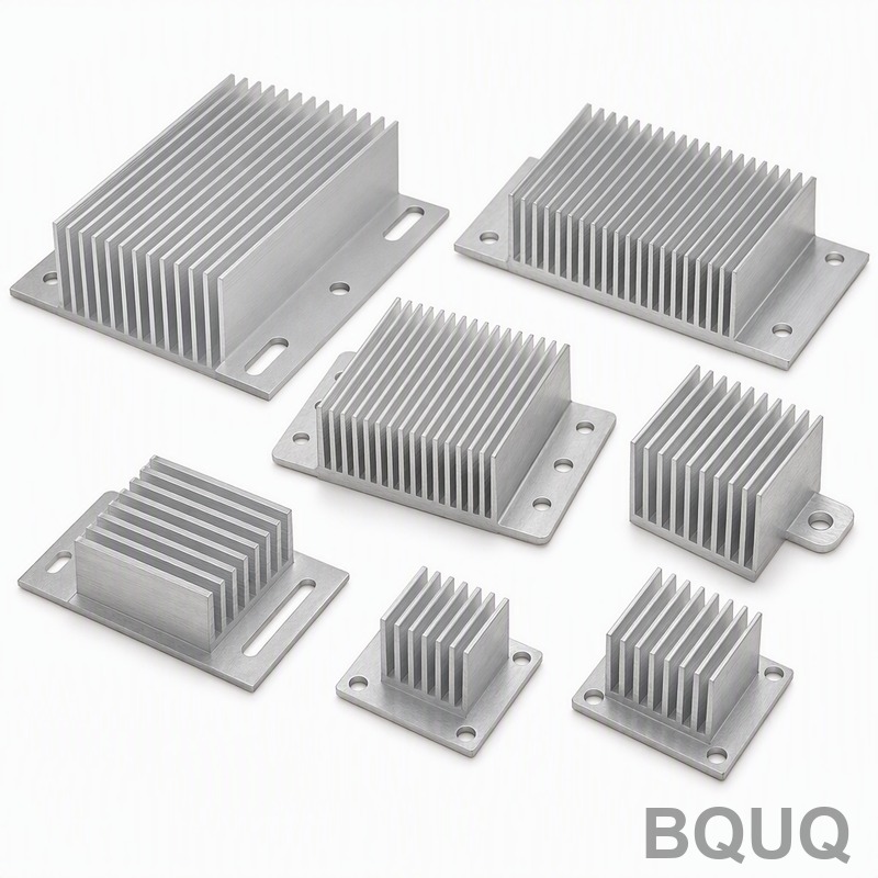
The thickness of a heat sink base directly determines its ability to spread heat laterally from a concentrated source to the fin array, with an optimal range typically falling between 3 mm and 8 mm for most forced-convection applications. A base that is too thin (below 2 mm) creates a thermal bottleneck where the hotspot temperature rises sharply, while an excessively thick base (above 12 mm) adds weight and cost without proportional thermal benefit due to the diminishing returns of lateral conduction. For a typical CPU cooler with a 30 mm x 30 mm heat source on a 90 mm x 90 mm base, increasing base thickness from 2 mm to 5 mm can reduce junction-to-ambient thermal resistance by 15% to 25%, but further increases to 10 mm yield only an additional 3% to 5% improvement.
What Is the Optimal Base Thickness for Different Heat Sink Types?
The optimal base thickness varies by cooling method and heat source size. For natural convection heat sinks, where airflow is minimal, a thicker base of 6 mm to 10 mm is recommended because lateral spreading must compensate for low convective heat transfer coefficients (5 to 15 W/m²K). For forced convection with fans (air velocity 2 to 5 m/s), a base of 3 mm to 6 mm is typically sufficient, as the fin efficiency handles most of the heat dissipation. For vapor chamber or heat pipe-assisted designs, the base can be reduced to 2 mm to 3 mm because the embedded heat pipes actively transport heat laterally. In LED lighting applications with small, high-flux sources (5 mm x 5 mm), the base should be at least 4 mm thick to prevent localized overheating, while large IGBT modules with 50 mm x 50 mm sources may require 8 mm to 12 mm of aluminum base to achieve uniform temperature distribution.
How Does Base Thickness Influence Thermal Resistance and Hotspot Temperature?
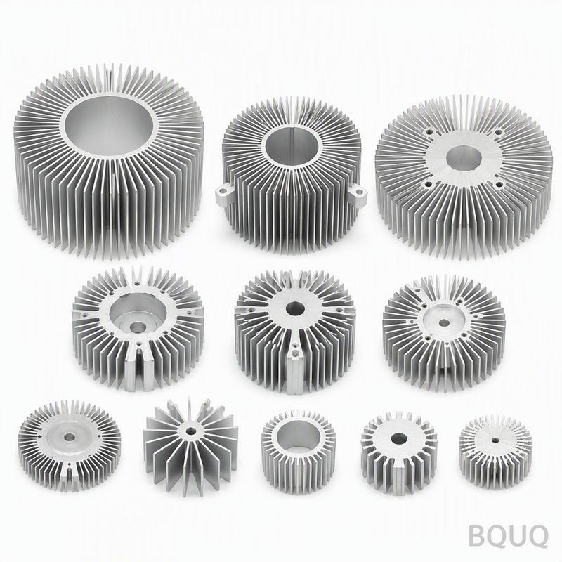
Thermal resistance is the primary metric for evaluating base thickness performance. The spreading resistance component, which dominates when the heat source is smaller than the base, decreases as thickness increases. For a 40 mm x 40 mm aluminum base (6063-T5, thermal conductivity 201 W/mK) with a 10 mm x 10 mm heat source dissipating 50 W, the spreading resistance drops from approximately 1.8 K/W at 2 mm thickness to 0.9 K/W at 5 mm thickness, and to 0.7 K/W at 8 mm thickness. This translates to a hotspot temperature reduction from 90°C to 72°C at 5 mm thickness under a 50°C ambient, assuming a convective resistance of 0.5 K/W. Beyond 8 mm, the improvement per millimeter of added material becomes negligible, typically less than 0.02 K/W per mm, making additional thickness economically inefficient for aluminum.
Why Does Material Thermal Conductivity Change the Required Base Thickness?
Material conductivity directly dictates the required thickness for effective heat spreading. Copper (thermal conductivity 385 W/mK) can achieve the same spreading performance as aluminum at roughly 40% of the thickness. For example, a 2 mm copper base provides equivalent lateral heat spreading to a 5 mm aluminum base in most applications. However, copper's higher density (8,960 kg/m³ versus 2,700 kg/m³ for aluminum) and cost (approximately 8 to 12 USD per kg versus 2 to 3 USD per kg for aluminum) limit its use to high-performance or space-constrained designs. For aluminum alloys, 6063-T5 is the most common choice for extruded heat sinks, but 1050 (conductivity 222 W/mK) offers lower cost at the expense of 10% lower conductivity. When selecting thickness, engineers should calculate the spreading resistance using the formula Rspread = 1/(2 * k * sqrt(A_source)) * (1 - sqrt(A_source/A_base))^1.5, which shows that for a given material, thickness beyond the characteristic length of the heat source provides minimal benefit.
Which Manufacturing Process Limits Base Thickness Options?
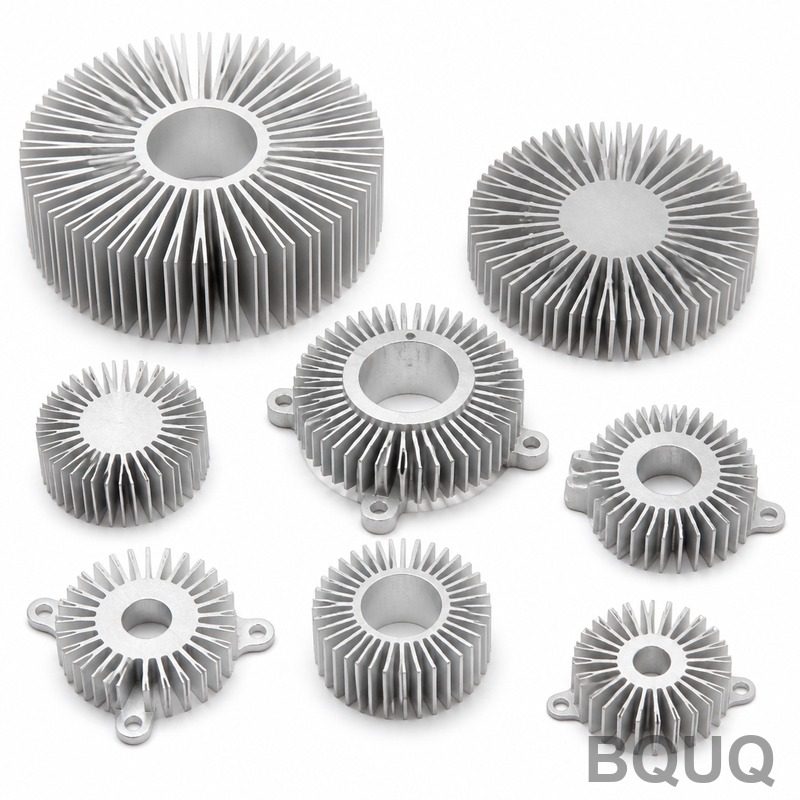
The manufacturing process constrains achievable base thickness and geometry. Extruded aluminum heat sinks can produce bases from 1.5 mm to 15 mm, but the extrusion ratio (billet diameter to profile cross-section) limits thin bases below 2 mm due to die strength and flow uniformity issues. CNC machining from solid aluminum billet allows precise base thickness control from 1 mm to 30 mm, with tolerance of plus or minus 0.05 mm, but adds cost of 3 to 8 USD per unit for machining time. Die-cast aluminum (A380 alloy, conductivity 96 W/mK) can achieve bases from 2 mm to 6 mm with good repeatability, but porosity can reduce effective conductivity by 10% to 15%. Skived or bonded fin heat sinks offer the thickest bases (up to 20 mm) because fins are cut from a solid block, but this process is limited to aluminum and costs 20% to 30% more than extrusion. For copper bases, only CNC machining or forging is practical, with minimum thickness of 2 mm to avoid warpage during cooling.
How Much Does Increasing Base Thickness Add to Material and Production Cost?
The cost impact of thicker bases follows a linear relationship for material but a non-linear relationship for machining and finishing. For an extruded aluminum heat sink measuring 100 mm x 100 mm x 40 mm total height, increasing base thickness from 3 mm to 6 mm adds approximately 40 grams of material, costing 0.10 to 0.15 USD per unit at current aluminum prices (2.5 USD per kg). CNC machining costs increase more significantly: each additional millimeter of base thickness adds 15 to 30 seconds of machining time, translating to 0.05 to 0.10 USD per unit at a shop rate of 60 USD per hour. Anodizing costs remain constant regardless of thickness, at approximately 0.02 to 0.05 USD per unit. For a production run of 10,000 units, increasing base thickness from 3 mm to 6 mm adds roughly 1,500 to 2,500 USD total, which is often justified if it reduces the required fin count or fan speed, saving system-level cost.
When Is a Thicker Base Actually Detrimental to Thermal Performance?
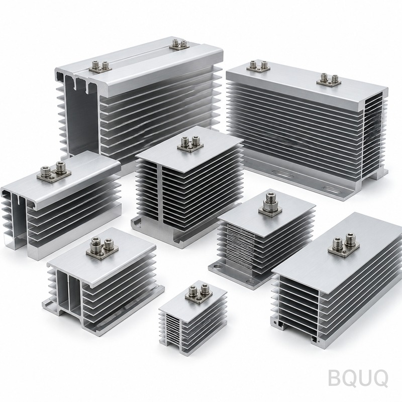
A thicker base becomes detrimental when it increases the vertical thermal path resistance without adding lateral spreading benefit, or when it interferes with airflow. In low-profile heat sinks (total height under 15 mm), a base thicker than 8 mm leaves insufficient fin height, reducing the total convective surface area by more than 30% and increasing overall thermal resistance despite better spreading. Additionally, in natural convection designs, a thick base increases the heat sink's mass and thermal capacitance, which slows the thermal response time, causing overheating during transient load spikes. For example, a 10 mm base in a 10 mm total height package leaves only zero fin height, rendering the heat sink ineffective. The rule of thumb is that base thickness should not exceed 30% of the total heat sink height, and for fin heights below 20 mm, the base should be kept under 5 mm to maintain adequate fin surface area.
What Is the Relationship Between Heat Source Area and Required Base Thickness?
The ratio of heat source area to base area dictates the minimum required thickness. When the heat source is smaller than 25% of the base area, spreading resistance dominates, and the base must be at least 5 mm to 8 mm thick for aluminum. When the heat source covers more than 70% of the base area, a 2 mm to 3 mm base is sufficient because heat travels primarily vertically. The characteristic spreading length is approximated by L = sqrt(A_source) / 2, and the base should be at least 1.5 times this value for optimal performance. For a 20 mm x 20 mm source on a 100 mm x 100 mm base, L = 10 mm, so a 15 mm base would theoretically be ideal, but practical constraints and diminishing returns suggest 8 mm as a cost-effective compromise. Engineers can use the spreading resistance formula to iterate thickness values and select the point where marginal improvement falls below 0.05 K/W.
| Base Thickness (mm) | Spreading Resistance (K/W) | Hotspot Temperature (°C) | Material Cost (USD/unit) | Recommended Use Case |
| 2 | 1.8 | 90 | 0.35 | Heat pipe assisted, small sources |
| 3 | 1.2 | 78 | 0.45 | Forced convection, LED modules |
| 5 | 0.9 | 72 | 0.60 | Standard CPU coolers, IGBT |
| 8 | 0.7 | 68 | 0.85 | Natural convection, large sources |
| 12 | 0.6 | 66 | 1.20 | High-flux density, passive cooling |
How Can Engineers Validate Base Thickness Through Simulation and Testing?
Finite element analysis (FEA) software such as ANSYS Icepak or FloTHERM should be used to simulate the thermal performance before prototyping. Set boundary conditions with a heat source of 50 W, ambient temperature of 25°C, and convective coefficient of 20 W/m²K for forced airflow. Mesh the base with at least three elements through the thickness direction to capture the temperature gradient accurately. After simulation, validate with a thermocouple mounted at the center of the heat source and at the base edge; the measured temperature difference should be within 5% of the simulated value. For production validation, perform a thermal impedance test using a standardized cold plate setup per JEDEC JESD51-14 standard, which specifies a 40 mm x 40 mm test area and a 10 mm x 10 mm heater. Test at three thicknesses (minimum, nominal, maximum) to confirm the manufacturing tolerance of plus or minus 0.1 mm does not shift thermal resistance by more than 3%.
FAQ
What Is the Standard Base Thickness for Aluminum Extruded Heat Sinks?
The standard base thickness for aluminum extruded heat sinks ranges from 3 mm to 6 mm, with 4 mm being the most common for general-purpose cooling. This thickness provides a balance between lateral heat spreading, material cost, and extrusion manufacturability. For high-performance applications, 6 mm to 8 mm is used, while thinner bases of 2 mm to 3 mm are reserved for heat pipe designs.
Can a Thicker Base Replace Additional Heat Pipes or Vapor Chambers?
A thicker base can partially replace heat pipes in low-power applications below 75 W, where spreading resistance is the dominant factor. However, for heat fluxes above 50 W/cm² or sources smaller than 10 mm x 10 mm, heat pipes are more effective because they provide active lateral transport with thermal conductivity equivalent to 5,000 to 10,000 W/mK. A thick base alone cannot match this performance without excessive weight.
How Does Base Thickness Affect Heat Sink Weight and Structural Integrity?
Each additional millimeter of base thickness on a 100 mm x 100 mm aluminum heat sink adds approximately 27 grams of weight. Structurally, a thicker base reduces the risk of warpage during thermal cycling, particularly for bases wider than 150 mm, where a minimum of 5 mm is recommended to prevent bending. However, for vibration-prone applications, the added mass can increase mechanical stress on mounting points.
What Tolerance Should Be Specified for Heat Sink Base Thickness?
For extruded aluminum heat sinks, specify a tolerance of plus or minus 0.15 mm for base thickness up to 6 mm, and plus or minus 0.20 mm for thicker bases. CNC machined bases can hold plus or minus 0.05 mm, which is necessary when the base interfaces with a thermal pad or phase-change material requiring precise flatness. Die-cast bases typically require plus or minus 0.25 mm due to shrinkage variation.
Does Base Thickness Impact the Effectiveness of Thermal Interface Materials?
Yes, a thicker base reduces the temperature gradient across the TIM because it lowers the thermal resistance of the heat sink itself, allowing the TIM to operate at lower temperatures. However, a thicker base also increases the total thermal mass, which can slow the warm-up time and affect the TIM's curing behavior if it is a phase-change material. For best results, keep the base thickness between 4 mm and 6 mm when using a TIM with a thermal conductivity of 5 W/mK or higher.
When Should Copper Be Used Instead of Thicker Aluminum for the Base?
Copper should be used when the available space above the heat source is limited to less than 15 mm total height, or when the heat flux exceeds 80 W/cm². A 2 mm copper base outperforms a 5 mm aluminum base in spreading capability while occupying less vertical space. Copper is also preferred when the heat sink must survive over 10,000 thermal cycles, as aluminum can fatigue at the base-to-fin junction.
How Does Base Thickness Interact with Fin Density and Fin Height?
Fin density and height must be balanced against base thickness because they compete for the same thermal budget and airflow path. High fin density (over 10 fins per inch) increases pressure drop, so a thicker base (6 mm to 8 mm) is needed to distribute heat to all fins evenly. Conversely, with low fin density (5 fins per inch), a 3 mm base is adequate because each fin handles a smaller heat load, reducing the need for lateral spreading.
In conclusion, the optimal heat sink base thickness is not a fixed value but a function of heat source size, material conductivity, airflow conditions, and manufacturing constraints. For most forced-convection aluminum heat sinks, a base thickness of 4 mm to 6 mm offers the best trade-off between thermal performance, weight, and cost, while natural convection and high-flux applications demand 8 mm or more. Engineers should always simulate and prototype at the selected thickness to verify spreading resistance and hotspot temperatures before committing to production tooling. BQUQ provides CNC machining, metal stamping, and extrusion services with 20 years of manufacturing experience, and we can help you optimize base thickness for your specific thermal load. Send us your CAD files or thermal requirements for a free engineering review and quotation within 12 hours. Contact us at sc@bquq.com or WhatsApp +86 13713157787, or visit www.bquq.com for more information.


