
How to Calculate Heat Sink Size for Electronics Thermal Design?
The direct answer: You calculate heat sink size by determining the total thermal resistance required from the junction to the ambient air, then selecting a heat sink whose thermal resistance (in °C/W) is equal to or lower than the calculated value. Specifically, the required heat sink resistance is (Tj_max - Ta_max) / P - Rjc - Rcs, where Tj_max is the maximum junction temperature, Ta_max is the maximum ambient temperature, P is the dissipated power, Rjc is the junction-to-case resistance, and Rcs is the case-to-sink interface resistance. For a typical 10W power dissipation with a 60°C ambient and a 125°C junction limit, you need a heat sink with approximately 4.5 °C/W or lower, which corresponds to a natural convection extruded aluminum profile of roughly 75mm x 75mm x 25mm.
What Is the Fundamental Equation for Heat Sink Sizing?
The core calculation is based on the thermal circuit analogy, where heat flows from the semiconductor junction to the ambient air through three series resistances: junction-to-case (Rjc), case-to-sink (Rcs), and sink-to-ambient (Rsa). The governing equation is Tj = Ta + P x (Rjc + Rcs + Rsa), which you rearrange to solve for the required sink-to-ambient resistance: Rsa = (Tj - Ta) / P - Rjc - Rcs. Every value in this equation must be in consistent units: temperature in degrees Celsius, power in watts, and thermal resistance in degrees Celsius per watt (°C/W). For example, a MOSFET with Rjc of 0.5 °C/W, using a 0.1 mm thermal pad with Rcs of 0.3 °C/W, dissipating 15W in a 50°C ambient with a 150°C junction limit, requires Rsa = (150 - 50)/15 - 0.5 - 0.3 = 5.87 °C/W.
How Do You Determine the Maximum Allowable Junction Temperature and Ambient Conditions?
The maximum junction temperature (Tj_max) is specified in the component datasheet and typically ranges from 125°C for silicon MOSFETs to 150°C for silicon carbide devices, with some automotive-grade parts rated at 175°C. You must always derate this value by 20-30% for reliability in long-life applications, meaning you should design for a target junction temperature of 85-100°C rather than the absolute maximum. The maximum ambient temperature (Ta_max) is the worst-case air temperature surrounding the heat sink, not the room temperature; for sealed enclosures, this can be 10-20°C higher than the external environment. For example, a power supply in a 40°C room inside a sealed metal box may see an internal ambient of 55-60°C, which is the value you must use in the calculation.
Which Thermal Resistance Values Do You Need from the Component Datasheet?
The junction-to-case thermal resistance (Rjc) is always listed in the component datasheet, typically under "Thermal Characteristics," and ranges from 0.2 °C/W for large TO-247 packages to 3.5 °C/W for small SOT-23 devices. The case-to-sink resistance (Rcs) depends on your interface material: a bare metal-to-metal contact with thermal grease gives 0.1-0.3 °C/W, a 0.25mm silicone pad gives 0.5-1.0 °C/W, and a mica washer with grease gives 0.4-0.8 °C/W. You must also account for the mounting pressure and surface flatness; typical extruded aluminum heat sinks have a flatness of 0.05 mm over 100 mm, which requires thermal interface material to fill micro-gaps. For high-power IGBT modules, Rcs with phase-change material can be as low as 0.02 °C/W when properly torqued to 3 N·m.
How Do You Calculate the Required Heat Sink Thermal Resistance with a Worked Example?
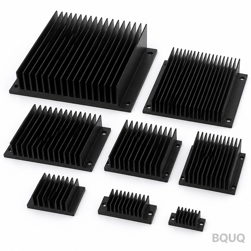
Consider a real example: a linear voltage regulator dissipating 20W, with a maximum junction temperature of 125°C, operating in a maximum ambient of 50°C. The datasheet gives Rjc = 1.0 °C/W for the TO-220 package, and you plan to use thermal grease with Rcs = 0.2 °C/W. The calculation is: Rsa = (125 - 50)/20 - 1.0 - 0.2 = 75/20 - 1.2 = 3.75 - 1.2 = 2.55 °C/W. You must select a heat sink with a thermal resistance of 2.55 °C/W or lower at your actual airflow condition; a natural convection extruded heat sink measuring 100mm x 100mm x 40mm with a 12mm base thickness typically provides 2.0-2.5 °C/W in free air. If you add forced air at 200 LFM (linear feet per minute), the same heat sink drops to approximately 0.8-1.0 °C/W, allowing you to use a much smaller profile.
What Is the Difference Between Natural Convection and Forced Air Cooling in Sizing?
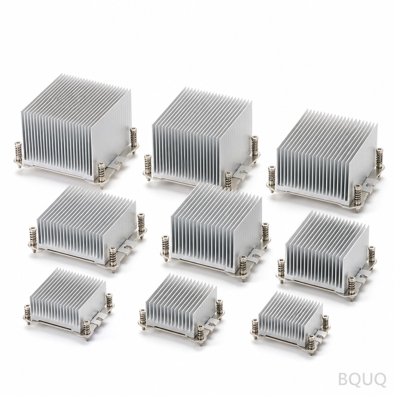
Natural convection heat sinks rely on buoyancy-driven airflow and typically achieve thermal resistances of 1.0-10 °C/W depending on size and fin geometry, with a practical limit of about 0.5 °C/W for very large passive heat sinks. Forced air cooling with a fan at 200-400 LFM can reduce thermal resistance by 50-70% compared to natural convection, but you must account for the fan's reliability, noise, and power consumption. The transition point is around 5-10W of dissipation for natural convection; above 10W, forced air becomes necessary for practical heat sink sizes. For example, a 50mm x 50mm x 25mm heat sink has about 5.5 °C/W in natural convection but drops to 1.8 °C/W at 300 LFM, meaning it can handle 18W instead of 6W for the same junction temperature rise.
How Do Heat Sink Dimensions and Fin Geometry Affect the Thermal Resistance?
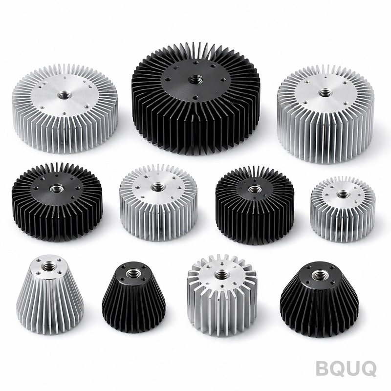
The thermal resistance of a heat sink is primarily determined by the total surface area, fin height, fin spacing, and base thickness. Fin spacing of 6-10 mm is optimal for natural convection, while 3-5 mm spacing works better for forced air, as tighter spacing restricts natural airflow. Fin height should be 10-25 mm for natural convection; taller fins beyond 25 mm give diminishing returns because the fin efficiency drops below 80%. Base thickness must be at least 5 mm for a 50mm x 50mm footprint to spread heat effectively; a 10-12 mm base is recommended for heat sources larger than 30mm in one dimension. The heat sink volume rule of thumb for natural convection is 10-15 cubic centimeters per watt, so a 10W application needs roughly 100-150 cc of aluminum volume, which corresponds to a 100mm x 100mm x 12mm profile.
What Are the Practical Steps to Verify Your Heat Sink Size Calculation?
After calculating the required Rsa, you must verify the selection using manufacturer datasheets, which list thermal resistance curves versus airflow for each extrusion profile. Always apply a safety factor of 1.2-1.5 to the calculated Rsa to account for dust accumulation, thermal aging of interface materials, and component-to-component variation; for example, if you calculated 2.55 °C/W, select a heat sink rated at 1.7-2.1 °C/W. You should also perform a thermal simulation using CFD tools such as FloTHERM or Icepak for complex geometries, but for simple plate-fin heat sinks, the analytical calculation with a 10-20% margin is sufficient. Finally, prototype and measure the actual junction temperature using a thermocouple on the case or an infrared camera; the measured temperature should be within 5-10°C of the calculated value, and if it is higher, you need a larger heat sink or improved airflow.
| Parameter | Natural Convection | Forced Air 200 LFM | Forced Air 400 LFM |
| Typical Rsa range | 1.0 - 10 °C/W | 0.5 - 3.0 °C/W | 0.3 - 1.5 °C/W |
| Max practical dissipation | 10 - 15 W | 30 - 50 W | 60 - 100 W |
| Recommended fin spacing | 6 - 10 mm | 4 - 6 mm | 3 - 5 mm |
| Heat sink volume per watt | 10 - 15 cm³/W | 4 - 7 cm³/W | 2 - 4 cm³/W |
| Typical cost per unit (100 pcs) | $2 - $8 | $4 - $15 (with fan) | $6 - $20 (with fan) |
| Example size for 10W | 100 x 100 x 25 mm | 50 x 50 x 25 mm | 40 x 40 x 15 mm |
When Should You Use a Heat Pipe or Liquid Cooling Instead of a Conventional Heat Sink?
When the calculated heat sink volume exceeds 500 cubic centimeters for natural convection or the required Rsa is below 0.2 °C/W with forced air, you should consider heat pipes or liquid cooling. Heat pipes have effective thermal conductivities of 5,000-10,000 W/m·K, allowing heat to be transferred from a small source to a large remote fin stack; they are ideal for CPU coolers and LED modules where space is constrained near the heat source. Liquid cooling systems achieve Rsa values of 0.05-0.15 °C/W with a 120mm radiator and pump, but add complexity, cost (typically $50-$150 per system), and maintenance. For most industrial electronics below 100W, a properly sized extruded aluminum heat sink with forced air is the most cost-effective solution, with a total system cost of $10-$30 including the fan.
What Materials and Manufacturing Processes Are Best for Heat Sinks?
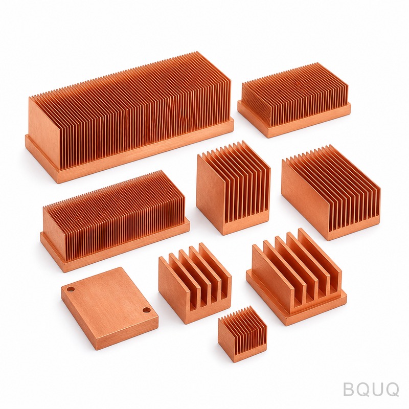
Extruded aluminum 6063-T5 is the industry standard for heat sinks because of its thermal conductivity of 200 W/m·K, low cost ($3-$5 per kilogram), and ease of extrusion into complex fin profiles. For higher performance, copper heat sinks offer 390 W/m·K but cost 3-4 times more and are 3 times heavier, so they are only used in space-constrained or high-flux applications. Skived fin heat sinks, made by cutting fins from a solid copper or aluminum block, achieve fin densities of 15-30 fins per inch with low thermal resistance, but cost $20-$80 each. Bonded fin and folded fin heat sinks are used for high-volume, low-cost applications where extrusion is not feasible; they have slightly higher thermal resistance due to the fin-to-base joint, typically adding 0.1-0.3 °C/W.
How Do You Account for Altitude and Enclosure Effects in Heat Sink Sizing?
At high altitudes above 1,000 meters, air density decreases, which reduces natural convection heat transfer by approximately 1% per 100 meters; at 3,000 meters, you need a heat sink 20-30% larger for the same performance. In sealed enclosures, the internal air temperature rises above the external ambient, and you must calculate the enclosure thermal resistance using the formula R_enclosure = 1/(h x A), where h is the convective coefficient (5-10 W/m²·K for natural convection on the enclosure walls) and A is the enclosure surface area. For a 0.5m x 0.5m x 0.2m sealed metal enclosure with a surface area of 0.7 m², the enclosure thermal resistance is approximately 0.2 °C/W, so if the electronics dissipate 50W, the internal ambient rises 10°C above the external air. You must add this temperature rise to your Ta_max value before performing the heat sink calculation.
What Is the Formula for Heat Sink Size Calculation?
The formula is Rsa = (Tj_max - Ta_max) / P - Rjc - Rcs, where Rsa is the required heat sink thermal resistance. For example, with Tj_max = 125°C, Ta_max = 50°C, P = 20W, Rjc = 1.0 °C/W, Rcs = 0.2 °C/W, you need Rsa = 2.55 °C/W.
How Much Surface Area Do I Need for a 10W Heat Sink?
For natural convection, you need approximately 100-150 cm² of exposed surface area per watt of dissipation. A 10W application therefore requires 1,000-1,500 cm² of fin surface area, which corresponds to a 100mm x 100mm x 25mm extruded heat sink with 10 fins.
What Is a Typical Thermal Resistance Value for a Standard Extruded Heat Sink?
A standard 100mm x 100mm x 25mm black anodized extruded heat sink has a thermal resistance of approximately 2.5-3.5 °C/W in natural convection. With forced air at 300 LFM, the same heat sink drops to 0.8-1.2 °C/W.
How Much Does a Custom Extruded Heat Sink Cost?
Custom extrusion tooling for a heat sink profile costs $1,500-$5,000 depending on complexity and die size. The per-unit cost for 1,000 pieces is typically $3-$8 each, with anodizing adding $0.5-$1.5 per unit and machining operations adding $2-$5 per unit.
When Should I Use an Anodized Heat Sink?
Anodizing improves the emissivity from 0.1 for bare aluminum to 0.85 for black anodized, which improves radiation heat transfer by up to 30% in natural convection applications. For forced air cooling, anodizing has minimal effect, and bare aluminum is acceptable, but anodizing also provides corrosion resistance.
Can I Use a Smaller Heat Sink If I Increase Airflow?
Yes, doubling the airflow from 200 to 400 LFM typically reduces thermal resistance by 30-50%. This allows you to use a heat sink that is 40-60% smaller by volume, but you must add the fan cost of $3-$10 and account for the fan failure risk.
What Is the Difference Between Thermal Resistance and Impedance?
Thermal resistance is a steady-state value measured at a constant power, while thermal impedance is a time-dependent value that includes transient behavior. For pulsed power loads, you use the transient thermal impedance curves from the datasheet to determine the peak temperature during the pulse, which may be lower than the steady-state temperature.
After completing your thermal design calculation, you need a manufacturing partner who can produce the heat sink to your exact specifications with the required tolerances and surface finish. BQUQ has 20 years of experience in CNC machining and aluminum extrusion for heat sinks, with the ability to hold tolerances of ±0.05 mm on critical dimensions and deliver prototype samples in 5-7 days. We provide free thermal design review and can recommend the optimal heat sink geometry for your application based on our in-house testing data. For a quotation within 12 hours, email your design files and thermal requirements to sc@bquq.com, contact us on WhatsApp at +86 13713157787, or visit www.bquq.com to submit your RFQ online.
Related Articles
- How to Attach a Heat Sink Without Screws: Thermal Adhesive Guide
- New energy vehicle IGBT heat dissipation, heat sink reliability engineering, heat pipe and temperature plate integrated heat sink, surface treatment and heat radiation enhancement: anodic oxidation, black coating and micro-nano structure, graphene/3D printing/intelligent thermal management: 2030 heat sink technology roadmap
- 5G Base Station Outdoor AAU Cooling: The Climate Adaptation Challenge of Fanless Passive Design


