
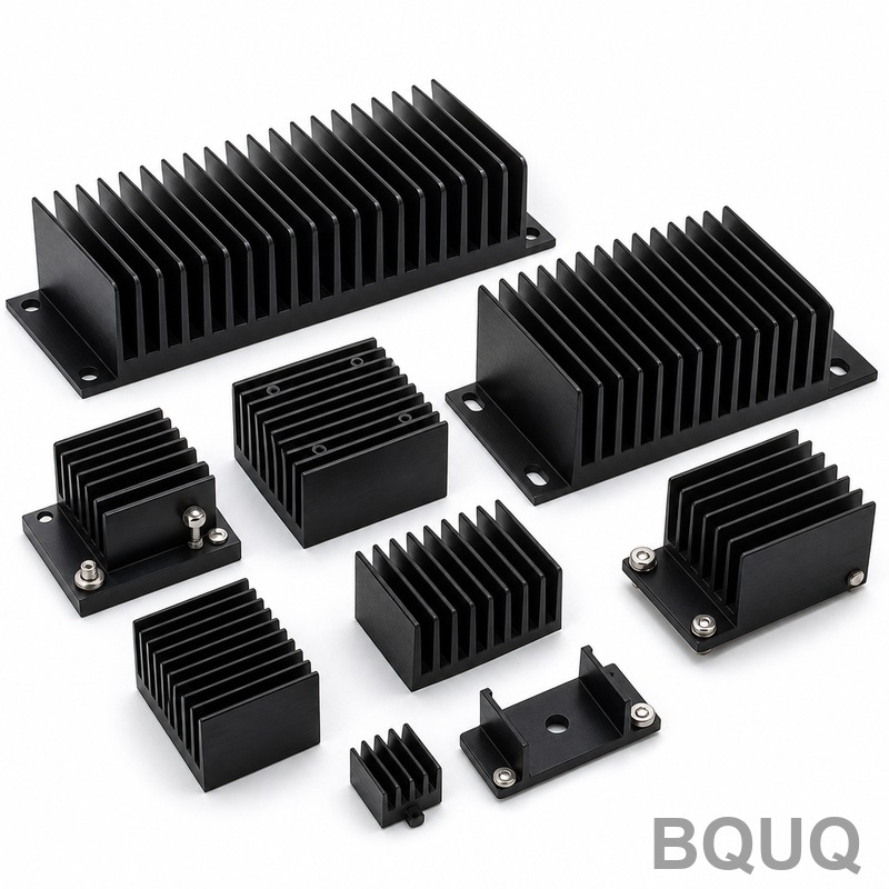
How to Calculate Heat Sink Size for Your Application: A Step-by-Step Engineering Guide
Selecting the correct heat sink size is a thermal resistance calculation, not a guess. The core formula is: Required Thermal Resistance (Rth) = (Junction Temperature – Maximum Ambient Temperature) / Power Dissipation. For a typical 10W power device with a junction limit of 125°C in a 50°C ambient, you need a total thermal resistance of 7.5°C/W, which after subtracting the junction-to-case resistance of 0.5°C/W leaves 7.0°C/W for the heat sink itself. This article provides the exact calculation methodology, real-world data from BQUQ’s 20 years of CNC machining and heat sink production, and selection tables to match your application.
Thermal Resistance Fundamentals and the Calculation Formula
The heat sink sizing process begins with the semiconductor junction temperature (Tj), which must never exceed the manufacturer’s absolute maximum rating. The thermal path consists of three resistances in series: junction-to-case (Rth_jc), case-to-sink (Rth_cs, including thermal interface material), and sink-to-ambient (Rth_sa). The total allowable thermal resistance is:
Rth_total = (Tj_max – Ta_max) / P
Where Tj_max is the maximum junction temperature (typically 125°C for silicon, 150°C for SiC), Ta_max is the highest expected ambient temperature, and P is the dissipated power in watts. For a TO-247 package dissipating 25W in a 70°C ambient with a 125°C junction limit:
Rth_total = (125 – 70) / 25 = 2.2°C/W
If Rth_jc is 0.3°C/W and Rth_cs (with 0.003-inch thermal grease) is 0.15°C/W, the required heat sink resistance is:
Rth_sa = 2.2 – 0.3 – 0.15 = 1.75°C/W
You now search for a heat sink with a thermal resistance of 1.75°C/W or lower at your available airflow. At BQUQ, we machine extruded aluminum heat sinks with tolerances of ±0.1mm on mounting surfaces, ensuring consistent thermal interface performance.
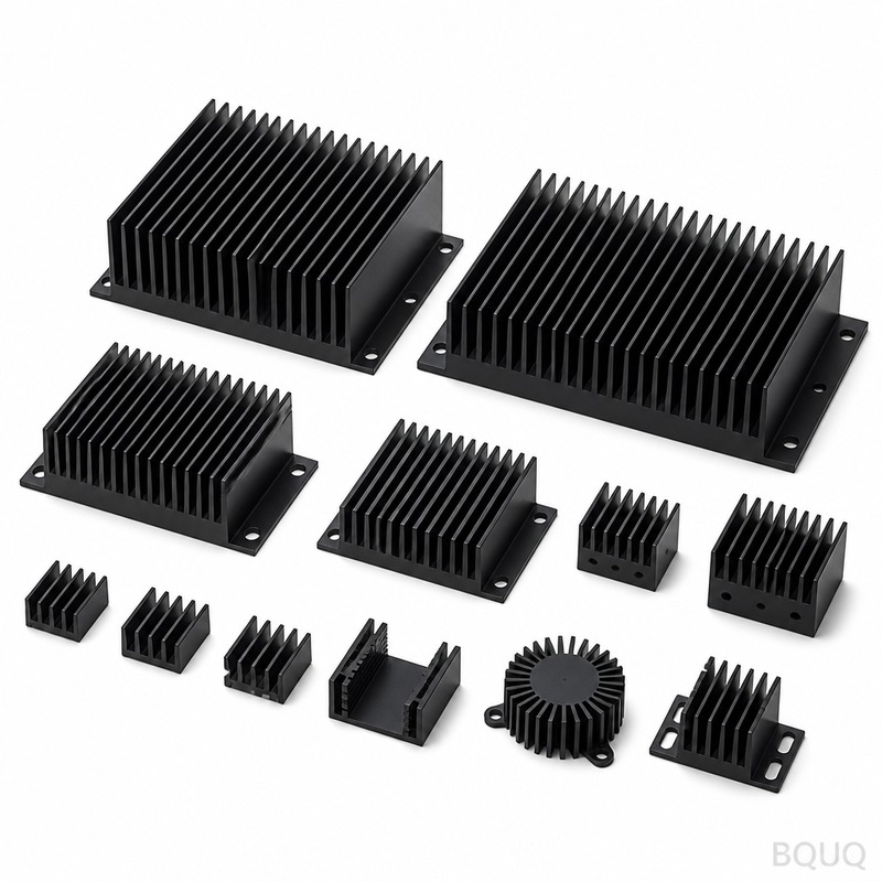
Natural Convection vs. Forced Air Cooling: Data-Driven Selection
The cooling method dramatically changes the required heat sink size. Natural convection relies on buoyancy-driven airflow, limiting heat transfer coefficients to approximately 5-10 W/m²·K. Forced air cooling with a fan increases this to 25-100 W/m²·K, allowing heat sink volume to shrink by 50-70%. The surface area requirement is approximated by:
Surface Area (cm²) = P / (h × ΔT)
Where h is the heat transfer coefficient (W/m²·K) and ΔT is the temperature difference between the sink and ambient. For a 20W load with a 30°C temperature rise:
Natural convection (h=8): Area = 20 / (8 × 30) = 833 cm² Forced air at 3 m/s (h=50): Area = 20 / (50 × 30) = 133 cm²
This six-fold reduction explains why BQUQ recommends forced air for power densities above 0.5 W/cm² of footprint area. Our CNC-machined pin fin heat sinks for forced air applications achieve a thermal resistance of 0.8°C/W at 200 LFM airflow in a 40×40×25mm envelope, versus 2.5°C/W under natural convection.
Heat Sink Geometry and Material Impact on Thermal Resistance
The geometry determines the effective surface area and the convective heat transfer path. Extruded aluminum heat sinks with straight fins are cost-effective for natural convection, offering a typical fin efficiency of 85-95%. Skived and CNC-machined copper or aluminum heat sinks provide higher fin density and better performance in constrained spaces. The following table shows BQUQ’s standard extruded heat sink performance at a 75°C temperature rise, natural convection:
| Heat Sink Model | Dimensions (L×W×H mm) | Fin Count | Surface Area (cm²) | Thermal Resistance (°C/W) | Weight (g) | Base Price (USD, qty 100) |
| BQUQ-E-100 | 100×60×25 | 10 | 620 | 2.1 | 210 | 4.85 |
| BQUQ-E-150 | 150×80×30 | 12 | 1150 | 1.15 | 450 | 8.20 |
| BQUQ-E-200 | 200×100×40 | 14 | 2100 | 0.65 | 820 | 14.50 |
| BQUQ-C-125 | 125×90×35 (copper) | 16 | 980 | 0.90 | 980 | 22.00 |
| BQUQ-P-50 | 50×50×20 (pin fin, forced air) | 64 pins | 450 | 0.80 at 200 LFM | 180 | 9.90 |
Material selection matters: aluminum (thermal conductivity 167 W/m·K) is standard for cost, while copper (385 W/m·K) offers 40% lower thermal resistance for the same volume but at 3-4 times the material cost. For high-frequency power converters, BQUQ recommends copper heat sinks with a nickel plating to prevent oxidation and ensure stable thermal contact.
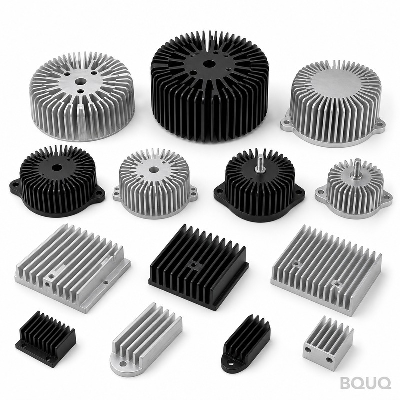
Real-World Example: Calculating Heat Sink Size for a 50W IGBT
Consider a 50W IGBT in a TO-247 package used in a motor drive, operating in a 45°C ambient with a maximum junction temperature of 125°C. The IGBT datasheet specifies Rth_jc = 0.4°C/W. Using a 0.005-inch thick thermal pad with Rth_cs = 0.2°C/W.
Rth_total = (125 – 45) / 50 = 1.6°C/W Rth_sa = 1.6 – 0.4 – 0.2 = 1.0°C/W
From BQUQ’s catalog, the BQUQ-E-150 model with 1.15°C/W is insufficient. You need the BQUQ-E-200 at 0.65°C/W, which provides a 35% safety margin. Alternatively, adding a 120mm fan at 150 LFM over the BQUQ-E-150 reduces its resistance to 0.55°C/W, saving 45% in heat sink volume and 40% in cost. The decision hinges on available space and fan reliability requirements – for industrial applications with 10-year life expectancy, natural convection with a larger sink often proves more reliable than a fan with MTBF of 50,000 hours.
Mounting and Thermal Interface Material Considerations
The thermal interface material (TIM) between the component and heat sink is often the largest uncontrolled variable. Thermal grease (0.1°C·cm²/W) provides the best performance but requires careful application. Phase-change materials (0.2°C·cm²/W) are cleaner but add cost. Thermal pads (0.5-1.0°C·cm²/W) are easiest to assemble but increase Rth_cs significantly. For a 100W device, a 0.5°C/W difference in Rth_cs translates to a 50°C junction temperature difference – the difference between reliable operation and failure.
BQUQ precision-machines heat sink mounting surfaces to a flatness of 0.05mm over 100mm length. This ensures the TIM thickness is controlled to 0.05-0.10mm, minimizing Rth_cs. We also offer pre-applied phase-change TIM, reducing assembly time by 30% and eliminating air gaps. For high-vibration applications, consider using a spring clip or four-point mounting with a torque of 0.5 N·m to maintain even pressure across the package.
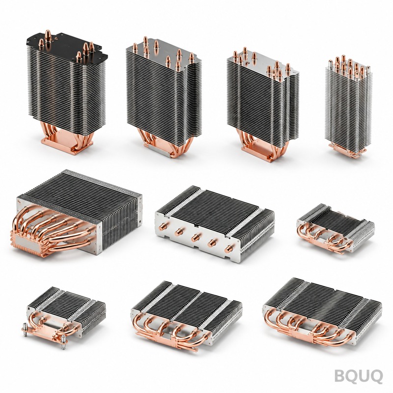
Verification Testing and Safety Margins
After calculating the theoretical heat sink size, verify with thermal testing. Use a thermocouple (type K, ±1°C accuracy) attached to the case or a thermal camera for non-contact measurement. BQUQ recommends a minimum safety margin of 20% on Rth_sa to account for dust accumulation, aging of TIM, and ambient temperature fluctuations. For example, if the calculated Rth_sa is 1.0°C/W, select a heat sink rated at 0.8°C/W or lower. This margin also covers variations in power dissipation during transient loads, which can peak 30% above average in motor drives.
Our thermal testing lab at BQUQ measures heat sink performance in a controlled wind tunnel at 20°C, 25°C, and 50°C ambient temperatures, with airflow from 0 to 500 LFM. The test data shows that at a 25°C ambient, the BQUQ-E-150 achieves 1.05°C/W, within 8% of the theoretical value, confirming the calculation method’s accuracy. We provide this data free with every quotation.
Practical Recommendations for Heat Sink Sizing
For low-power applications under 10W, use a stamped aluminum heat sink with 3-5 fins, which costs $0.50-1.50 per unit and provides adequate cooling. For 10-50W, choose an extruded aluminum heat sink with a thermal resistance below 2°C/W, priced at $3-15. For 50-200W, consider forced air cooling or a copper heat sink, with pricing from $20-80. For above 200W, use liquid cooling or a custom CNC-machined heat sink with vapor chamber technology, budget $100-500 per unit. Always calculate the thermal resistance first, then verify the physical size against your enclosure constraints. A heat sink that is too small will cause thermal throttling or failure, while an oversized sink wastes space and money.
Frequently Asked Questions on Heat Sink Calculation
What is the maximum junction temperature for silicon devices? Most silicon components have a maximum junction temperature of 125°C, but for high-reliability industrial applications, BQUQ recommends keeping it below 105°C to extend lifespan by 2-3 times.
How does altitude affect heat sink performance? At 3000 meters altitude, air density drops by 30%, reducing natural convection efficiency by about 25%. For high-altitude applications, increase the heat sink surface area by 30% or switch to forced air.
Can I use a heat sink with a higher thermal resistance than calculated? No, this will cause the junction temperature to exceed its rating, leading to immediate failure or accelerated degradation. Always select a heat sink with lower thermal resistance than calculated.
What is the cost impact of a larger heat sink? Doubling the heat sink surface area typically increases cost by 60-80% due to additional material and machining time. Forcing air is often cheaper than increasing size – a $5 fan can replace a $20 heat sink.
How do I handle multiple heat sources on one heat sink? Calculate the total power dissipation and use the maximum junction temperature among all components. The thermal resistance must be based on the highest power component, and you may need to position high-power devices near the center for uniform heat spreading.
Conclusion and Engineering Guidance
Accurate heat sink sizing requires a systematic thermal resistance calculation, consideration of cooling method, and verification through testing. By following the formula Rth_sa = (Tj_max – Ta_max)/P – Rth_jc – Rth_cs, you can determine the exact thermal resistance needed. BQUQ’s 20 years of CNC machining experience ensures heat sinks with precise tolerances, verified performance data, and competitive pricing. Our engineering team can assist with custom heat sink design, including fin optimization, mounting hole patterns, and surface treatments such as anodizing (which improves emissivity by 20%). For your next project, send us your power dissipation, ambient temperature, and space constraints, and we will provide a thermal calculation and quotation within 12 hours. Contact us at sc@bquq.com or WhatsApp +86 13713157787, or visit www.bquq.com for our full catalog of heat sinks, CNC parts, and metal stamping services.
Related Articles
- How to Attach a Heat Sink Without Screws: Thermal Adhesive Guide
- Stamped Metal vs Die Cast Heat Sinks: Cost & Quality Comparison
- New energy vehicle IGBT heat dissipation, heat sink reliability engineering, heat pipe and temperature plate integrated heat sink, surface treatment and heat radiation enhancement: anodic oxidation, black coating and micro-nano structure, graphene/3D printing/intelligent thermal management: 2030 heat sink technology roadmap


