
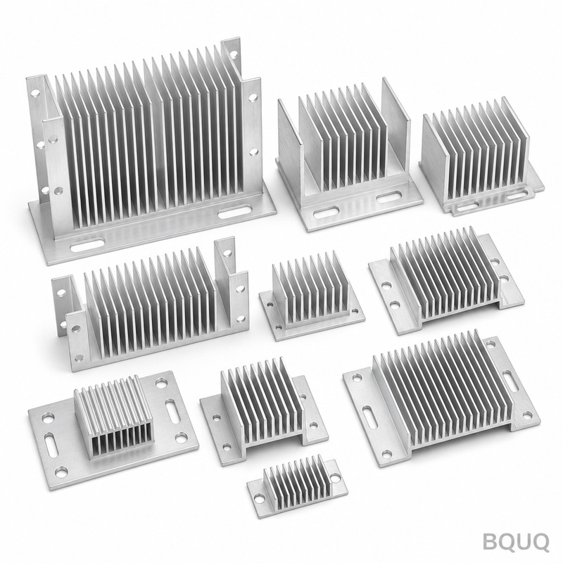
How to Calculate Heat Sink Size for Your Electronic Enclosure
The Direct Answer
To calculate heat sink size for an electronic enclosure, you must determine the total thermal resistance required (Rth, in °C/W) using the formula Rth = (Tj_max - Ta_max - P × Rth_jc - P × Rth_cs) / P, where P is total dissipated power in watts, Tj_max is the maximum junction temperature (typically 125°C for silicon), Ta_max is the maximum ambient temperature inside the enclosure (often 40-70°C), Rth_jc is junction-to-case resistance (from datasheet), and Rth_cs is case-to-sink resistance (typically 0.1-0.5°C/W with thermal paste). Once you have the required Rth, select a heat sink with a thermal resistance at or below that value, then verify the enclosure's internal airflow and mounting constraints. For a typical 50W power supply in a sealed 5mm aluminum enclosure with 50°C ambient, you will need a heat sink with Rth of approximately 1.0-1.5°C/W, which translates to a 150mm x 100mm x 40mm extruded aluminum finned profile.
Thermal Resistance Chain and the Governing Equation
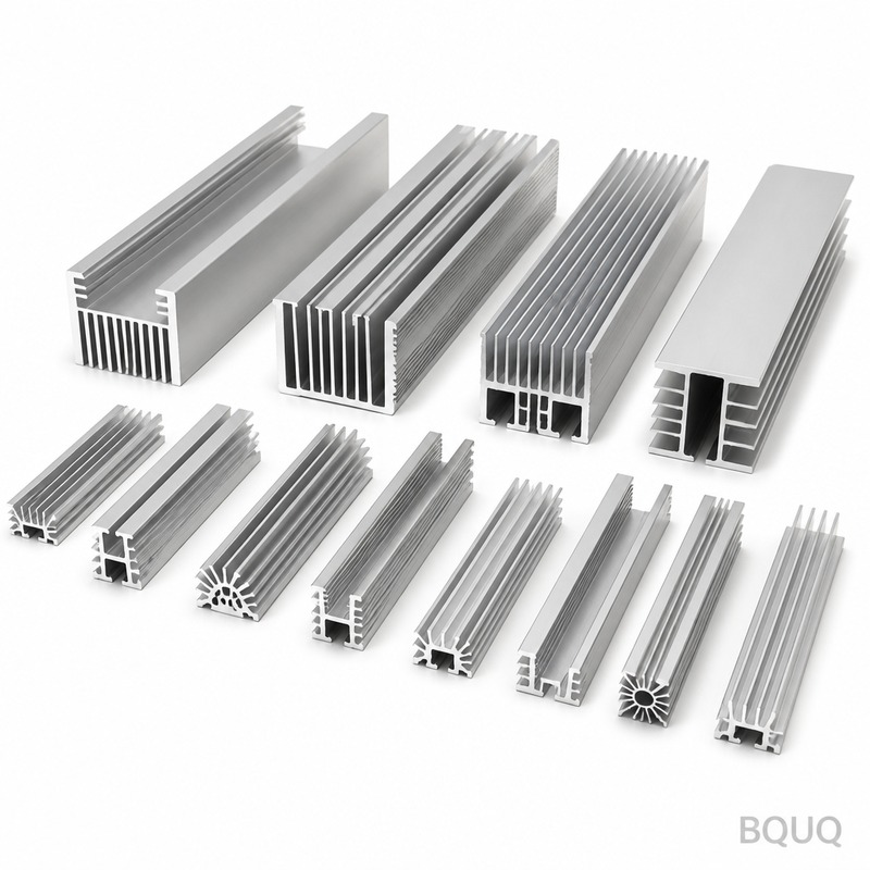
Every electronic enclosure has a thermal path from the semiconductor junction to the external environment. This path consists of four resistances in series: junction-to-case (Rth_jc), case-to-sink (Rth_cs), sink-to-ambient (Rth_sa), and in some cases, enclosure wall resistance. The total system resistance is the sum of all these values. The maximum allowable total resistance is calculated as:
Rth_total = (Tj_max - Ta_max) / P
For example, with an IGBT module rated at Tj_max = 150°C, Ta_max = 45°C inside the enclosure, and P = 200W, the total allowable resistance is (150 - 45) / 200 = 0.525°C/W. If the module's Rth_jc is 0.12°C/W and the thermal interface material contributes 0.05°C/W, the heat sink must provide no more than 0.525 - 0.12 - 0.05 = 0.355°C/W. This is a substantial heat sink. BQUQ recommends always adding a safety factor of 15-20% to the calculated Rth to account for thermal aging of thermal paste and dust accumulation on fins, meaning your target Rth_sa should be 0.28-0.30°C/W in this case.
Enclosure Volume and Internal Air Temperature Rise
The enclosure's internal air temperature is not equal to the external ambient. Sealed enclosures can have internal temperatures 15-30°C higher than the outside environment due to trapped heat. The internal temperature rise is approximated by:
ΔT_internal = P × Rth_enclosure_wall
For a 3mm thick aluminum enclosure with 0.5m² surface area, the wall thermal resistance is approximately 0.5°C/W. A 100W heat source inside will raise the internal air temperature by 50°C above external ambient. This is why many engineers mistakenly undersize heat sinks by using external ambient temperature instead of internal ambient. To accurately calculate heat sink size, you must model the enclosure as a pre-heater. If your external ambient is 35°C and the internal rise is 50°C, your heat sink sees an ambient of 85°C, not 35°C. This triples the required heat sink volume. For ventilated enclosures with fan-assisted airflow of 100-200 CFM, the internal rise drops to 5-10°C, allowing a heat sink roughly 40-60% smaller.
Heat Sink Geometry, Fin Spacing and Material Selection
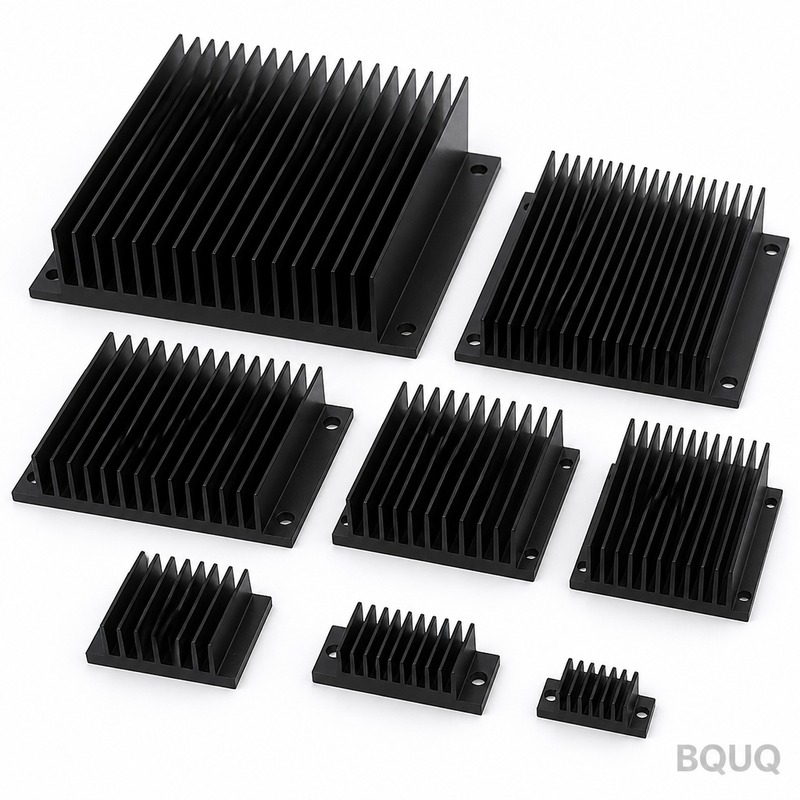
The physical dimensions of your heat sink are driven by the required Rth_sa and the available airflow. Natural convection heat sinks use wider fin spacing (8-12mm pitch) because air movement is driven by buoyancy; tight fin spacing restricts natural flow. Forced convection heat sinks with airflow of 2-5 m/s can use fin spacing of 4-6mm, increasing surface area per volume by up to 60%. The table below shows typical performance for extruded aluminum 6063-T5 heat sinks at various sizes and airflow conditions:
| Heat Sink Size (LxWxH mm) | Fin Count | Surface Area (cm²) | Rth Natural Convection (°C/W) | Rth Forced Air 2.5 m/s (°C/W) | Approx. Price (USD, qty 100) |
| 100x60x25 | 6 | 420 | 3.8 | 1.2 | 2.10 |
| 150x100x40 | 10 | 1150 | 1.6 | 0.45 | 5.80 |
| 200x120x50 | 14 | 2100 | 0.85 | 0.22 | 9.40 |
| 250x150x60 | 18 | 3400 | 0.55 | 0.13 | 15.20 |
| 300x200x80 | 24 | 5800 | 0.32 | 0.07 | 28.50 |
Material selection matters: 6063-T5 aluminum has a thermal conductivity of 201 W/m·K, while 6061-T6 has 167 W/m·K. For heat sinks over 150mm in length, the spread of heat from the base to the fin tips becomes significant; 6063-T5 is the industry standard for extruded heat sinks because of its superior conductivity and extrudability. Copper heat sinks (385 W/m·K) are used only for high-power density applications above 500W or where space is extremely limited, but they cost 3-4 times more and are 3 times heavier. BQUQ's standard production tolerance for extruded heat sink flatness is 0.05mm per 100mm length, and base surface roughness is Ra 1.6μm, which is adequate for thermal interface materials with 0.05mm bond line thickness.
Real-World Calculation Example with BQUQ Specifications
Consider a 48V DC-DC converter producing 150W of heat in a ventilated enclosure with internal ambient of 55°C. The MOSFETs have Tj_max = 125°C and Rth_jc = 0.4°C/W. With a thermal pad providing Rth_cs = 0.15°C/W, the remaining budget for the heat sink is:
Rth_sa = (125 - 55) / 150 - 0.4 - 0.15 = 0.4667 - 0.55 = -0.083°C/W
This negative result means no passive heat sink can work. You must either reduce power dissipation, lower Tj_max requirement, or add forced airflow. If you increase airflow to 4 m/s, the 200x120x50mm heat sink from the table above provides 0.22°C/W, giving a junction temperature of:
Tj = 55 + 150 × (0.22 + 0.4 + 0.15) = 55 + 150 × 0.77 = 55 + 115.5 = 170.5°C
This still exceeds 125°C. You need a bigger heat sink or multiple sinks. Using the 300x200x80mm unit at 0.07°C/W under forced air:
Tj = 55 + 150 × (0.07 + 0.4 + 0.15) = 55 + 150 × 0.62 = 55 + 93 = 148°C
Still too high. The solution is to mount two 250x150x60mm heat sinks in parallel on opposite enclosure walls, each handling 75W. Each sees Rth_sa = 0.55°C/W (natural convection) or 0.13°C/W (forced air). With natural convection:
Tj = 55 + 75 × (0.55 + 0.4 + 0.15) = 55 + 75 × 1.10 = 55 + 82.5 = 137.5°C
This is close. With forced air at 2.5 m/s:
Tj = 55 + 75 × (0.13 + 0.4 + 0.15) = 55 + 75 × 0.68 = 55 + 51 = 106°C
This is a safe margin of 19°C below the 125°C limit. This example demonstrates that heat sink sizing is iterative and often requires multiple sinks or active cooling.
Mounting, Thermal Interface Materials and Mechanical Tolerances
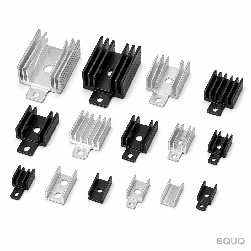
The interface between the heat sink and the component is often the weakest link. BQUQ recommends using thermal grease with thermal conductivity of 1.5-3.0 W/m·K at a bond line thickness of 25-50μm. The contact pressure should be 10-30 psi for optimal performance. If using a thermal pad, choose one with 3-6 W/m·K conductivity and match the pad's hardness (Shore A 20-40) to the component's surface flatness. The heat sink base must be flat to 0.05mm/100mm, and the component's case flatness is typically 0.02-0.05mm. Any air gap increases Rth_cs dramatically; a 0.1mm air gap has thermal resistance of approximately 0.003°C·m²/W, which can add 0.3-0.5°C/W to a 100x100mm interface. For high-volume production, BQUQ offers heat sinks with pre-applied phase-change materials that melt at 45-55°C, filling all micro-gaps upon first power-up. These materials reduce Rth_cs by 30-40% compared to dry mounting. Screw torque for M3 mounting screws should be 0.6-0.8 N·m, and for M4 screws, 1.2-1.5 N·m to avoid warping the base.
Practical Recommendations and Common Sizing Mistakes
First, always measure the actual power dissipation with a power analyzer rather than relying on datasheet efficiency claims; real-world efficiency is 2-5% lower than datasheet values. Second, never use the external ambient temperature for calculations in sealed enclosures; use the internal temperature after 30 minutes of operation, which you can measure with a thermocouple. Third, orient the heat sink fins vertically for natural convection; horizontal fin orientation reduces performance by 20-30% because air cannot rise through the channels. Fourth, if your enclosure has a fan, place the heat sink in the direct airflow path, not behind other components. Fifth, consider the heat sink's weight for vibration environments; a 300x200x80mm aluminum heat sink weighs 2.8kg, and you may need additional mounting brackets to prevent fatigue failure at solder joints. Sixth, for PCB-mounted heat sinks, use through-hole mounting with 1.6mm thick PCB, and ensure the heat sink's weight does not exceed 50g without additional mechanical support. Finally, always prototype and test with thermocouples at the case, heat sink base, and fin tip; the calculated values are a starting point, not the final answer. BQUQ's engineering team uses computational fluid dynamics (CFD) simulations for enclosures above 200W thermal load, which typically predict temperatures within 5°C of actual measurements.
Conclusion and Next Step
Accurate heat sink sizing hinges on calculating the required thermal resistance from the junction to the ambient, accounting for internal enclosure temperature rise, and then selecting a fin profile that matches your airflow conditions. The most common error is using external ambient instead of internal ambient, leading to undersized heat sinks and premature component failure. For a 100W dissipation in a ventilated enclosure, expect to need a 150x100x40mm extruded aluminum heat sink with forced airflow, costing $5-9 per unit at production volumes. For natural convection only, double the volume to 200x120x50mm, costing $9-14 per unit. Always add a 20% safety margin and verify with thermal testing.
BQUQ has manufactured precision heat sinks for over 20 years with CNC machining tolerances of ±0.02mm and surface finishes of Ra 0.8μm on the mounting surface. We provide free thermal simulation and design recommendations based on your enclosure dimensions, power dissipation, and airflow. Send us your power budget and enclosure drawings for a same-day feasibility check. Our quoting team responds within 12 hours with pricing and lead time.
| Email: sc@bquq.com | WhatsApp: +86 13713157787 | www.bquq.com |
Related Articles
- How to Attach a Heat Sink Without Screws: Thermal Adhesive Guide
- New energy vehicle IGBT heat dissipation, heat sink reliability engineering, heat pipe and temperature plate integrated heat sink, surface treatment and heat radiation enhancement: anodic oxidation, black coating and micro-nano structure, graphene/3D printing/intelligent thermal management: 2030 heat sink technology roadmap
- 5G Base Station Outdoor AAU Cooling: The Climate Adaptation Challenge of Fanless Passive Design


