
How to Calculate Thermal Resistance in Heat Sink Design for Reliable Performance?
The direct answer is that you calculate thermal resistance (Rth) by dividing the temperature difference between the heat source and the ambient air by the power dissipated (Rth = ΔT / P). For a practical heat sink design, you must sum the individual resistances from the junction to the case, case to the sink, and sink to ambient, then compare that total against your maximum allowable junction temperature. This calculation determines whether a standard extruded aluminum profile, a bonded fin assembly, or a liquid-cooled cold plate is necessary for your application.
What Is the Fundamental Formula for Thermal Resistance Calculation?
The governing equation for any heat sink design is the thermal resistance formula, expressed as Rth = (Tj - Ta) / P, where Tj is the junction temperature, Ta is the ambient temperature, and P is the heat load in watts. In practice, engineers use the extended form: Tj = Ta + P x (Rth_jc + Rth_cs + Rth_sa), where Rth_jc is the junction-to-case resistance (provided by the component manufacturer), Rth_cs is the case-to-sink resistance (dominated by the thermal interface material), and Rth_sa is the sink-to-ambient resistance (the value you are designing). For example, if you have a 50-watt IGBT with a maximum junction temperature of 150°C and an ambient temperature of 50°C, your total allowable resistance is (150 - 50) / 50 = 2.0°C/W. If the component's Rth_jc is 0.5°C/W and your TIM provides 0.1°C/W, your heat sink must achieve a maximum Rth_sa of 1.4°C/W.
How Do You Determine the Required Sink-to-Ambient Resistance (Rth_sa)?
The sink-to-ambient resistance is the most critical value you control, and it is calculated by subtracting the known resistances from your total allowable budget. Using the previous example, Rth_sa = 2.0 - 0.5 - 0.1 = 1.4°C/W. This target value directly dictates the physical size, fin geometry, and airflow requirements of your heat sink. For natural convection (no fan), a typical extruded aluminum heat sink with a 100mm x 100mm base and 25mm fin height might offer an Rth_sa of approximately 2.5°C/W for a 75-watt load. To achieve 1.4°C/W, you would need to increase the surface area by roughly 60%, add forced air at 2 m/s (which can reduce Rth_sa by 50-70%), or switch to a copper base plate due to its 401 W/m·K thermal conductivity versus aluminum's 180-200 W/m·K.
Why Must You Factor in the Thermal Interface Material (TIM) Resistance?
The case-to-sink resistance (Rth_cs) is often the most underestimated value in heat sink calculations, yet it can account for 10-30% of the total thermal budget. A dry interface with a 25mm x 25mm IGBT package has an Rth_cs of approximately 0.5°C/W due to air gaps, whereas applying a 0.05mm layer of thermal grease (with a thermal conductivity of 3 W/m·K) reduces this to 0.1°C/W. Phase-change materials and graphite pads offer similar performance at 0.08-0.15°C/W for the same area, but they require consistent mounting pressure of 20-50 psi. For high-reliability designs, we recommend using a 0.25mm thick aluminum nitride ceramic pad with a thermal conductivity of 170 W/m·K, which provides electrical isolation and an Rth_cs of 0.2°C/W for a TO-247 package, ensuring that the calculation does not fail due to installation variables.
How Does Airflow Velocity Affect the Final Thermal Resistance?
Airflow is the single most impactful variable in forced convection heat sink design, and it follows a non-linear relationship with thermal resistance. At 0 m/s (natural convection), a typical 150mm x 100mm x 40mm aluminum heat sink might have an Rth_sa of 0.8°C/W. Increasing airflow to 1 m/s reduces this to 0.4°C/W, a 50% improvement. At 3 m/s, the resistance drops further to 0.25°C/W, but doubling airflow to 6 m/s only yields 0.20°C/W, demonstrating diminishing returns. This relationship follows the empirical formula Rth_sa = C / (Airflow)^0.5 for turbulent flow, where C is a constant based on fin geometry. For BQUQ's production heat sinks, we typically recommend a fin pitch of 8-10mm for natural convection and 4-6mm for forced air above 2 m/s, as tighter pitches below 4mm become ineffective due to boundary layer interference.
Which Material and Manufacturing Process Offers the Best Thermal Performance per Cost?
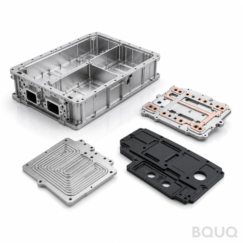
Aluminum 6063-T5 extrusion is the industry standard for 80% of heat sink applications because it balances thermal conductivity (201 W/m·K), cost (approximately $3-5 per kg in raw form), and manufacturability. For high-density applications exceeding 100 W/cm², copper heat sinks with a conductivity of 401 W/m·K are used, but they cost 3-4 times more and weigh 3.3 times more, complicating mounting and vibration testing. Skived fin technology (cut from solid copper or aluminum) can achieve fin heights up to 75mm with fin thicknesses of 0.5mm, offering a 30% lower Rth_sa than equivalent extruded profiles. For volume production, BQUQ uses CNC machining for custom base plates and heat pipes for heat spreading, where a 6mm diameter sintered heat pipe can transport up to 50 watts over a 200mm length with a temperature drop of only 2-3°C.
| Cooling Method | Typical Rth_sa (C/W) | Max Heat Flux (W/cm2) | Relative Cost | Lead Time (BQUQ) |
| Natural Convection Extrusion | 0.5 - 3.0 | 5 - 15 | 1x | 2-3 weeks |
| Forced Air (2 m/s) Extrusion | 0.2 - 0.8 | 20 - 60 | 1.3x | 2-3 weeks |
| Skived Fin (Forced Air) | 0.1 - 0.3 | 40 - 100 | 2.5x | 3-4 weeks |
| Copper Base + Heat Pipes | 0.05 - 0.15 | 80 - 200 | 4x | 4-5 weeks |
| Liquid Cold Plate | 0.02 - 0.05 | 200 - 500 | 6x | 5-6 weeks |
How Do You Account for Altitude and Orientation in the Calculation?
Ambient conditions such as altitude and mounting orientation can shift your calculated Rth_sa by 15-40%, and neglecting them leads to premature thermal failure. At an altitude of 3000 meters, air density drops by 30%, reducing the heat transfer coefficient for convection by approximately 20%, so you must multiply your target Rth_sa by 1.2 for natural convection designs. Orientation also matters: a heat sink with vertical fins mounted horizontally will have a 15-25% higher Rth_sa than when mounted vertically, because natural convection relies on buoyancy-driven airflow along the fin length. For BQUQ's standard 100mm x 100mm x 25mm extrusion, the Rth_sa is 2.8°C/W in a vertical orientation and 3.4°C/W horizontal, at sea level. If your product will be used at high altitude, we recommend derating the power by 15% or adding a low-speed fan at 1 m/s to compensate.
When Should You Use Numerical Simulation Instead of Hand Calculations?
Hand calculations using the formulas above are accurate within 10-15% for standard extruded geometries, but they fail when the heat source is localized, the fin geometry is non-uniform, or there are multiple heat sources. For a CPU with a 20mm x 20mm die on a 100mm x 100mm heat sink base, the spreading resistance alone can add 0.2-0.4°C/W that simple one-dimensional calculations miss. In these cases, computational fluid dynamics (CFD) simulation, such as Flotherm or Ansys Icepak, is necessary to predict the temperature distribution with an accuracy of ±2-3°C. BQUQ offers CFD validation for all custom heat sink designs at no charge during the quoting phase, and we recommend simulation whenever the heat flux exceeds 50 W/cm² or when the product must meet strict safety certifications like UL or IEC standards where a 10% error is unacceptable.
Conclusion
Calculating thermal resistance in heat sink design is a straightforward process of budgeting your allowable temperature rise and dividing by the power dissipation, but success lies in accurately estimating each sub-resistance value. You must combine the manufacturer's junction-to-case data, a realistic TIM resistance, a targeted sink-to-ambient value, and derating factors for airflow, altitude, and orientation. For production volumes above 500 pieces, we recommend partnering with a manufacturer that can provide validated Rth_sa curves from wind tunnel testing, as this eliminates the guesswork and ensures your design meets its thermal specification on the first prototype.
FAQ
What Is a Typical Junction-to-Case Resistance for a Power MOSFET?
A typical TO-220 package has an Rth_jc of 3.5°C/W, while a TO-247 package offers 0.5°C/W, and a D2PAK surface-mount device is around 1.0°C/W. These values are specified in the datasheet and are measured with the case at 25°C. You must always use these values directly, as they account for the internal die attach and lead frame materials.
How Much Does a Custom Extruded Heat Sink Cost?
For a standard 150mm x 100mm x 40mm profile, the tooling cost is between $800 and $1,500, and the per-part cost is $4-8 for quantities of 1,000 pieces. Tooling for a simple profile typically takes 2 weeks, with production samples following in 1-2 weeks. More complex shapes with undercuts or multiple chambers will increase tooling cost by 50%.
Can I Use Thermal Pads Instead of Grease for a 100-Watt Application?
Yes, but you must select a pad with a thermal conductivity of at least 5 W/m·K and ensure a mounting pressure of 30-50 psi to achieve an Rth_cs of 0.1°C/W. Silicone pads are easier to handle than grease and provide consistent thickness, but they have a higher thermal resistance if pressure is not applied evenly. For a 100-watt load, a 0.3°C/W error from a poor pad interface will raise the junction temperature by 30°C, which is often catastrophic.
What Is the Maximum Fin Height for an Aluminum Extrusion?
Standard aluminum extrusion can achieve fin heights up to 150mm with a fin thickness of 1.5mm and a pitch of 5mm, but the effective fin efficiency drops above 50mm. For fins taller than 75mm, the material at the tip conducts heat poorly, so a skived fin design is more efficient. BQUQ recommends a maximum fin height of 60mm for extruded profiles to maintain a fin efficiency above 85%.
When Is a Liquid Cold Plate Necessary Instead of an Air-Cooled Heat Sink?
A liquid cold plate is necessary when the heat load exceeds 500 watts or the allowable Rth_sa is below 0.05°C/W, which is impossible with air cooling. For example, a 1kW IGBT module with a 40°C ambient requires a total resistance of 0.11°C/W, and even a large air-cooled heat sink can only reach 0.15°C/W. Liquid cooling with a 1 L/min flow rate can achieve 0.03°C/W, making it mandatory for high-power density applications like EV inverters and laser diodes.
How Do I Calculate the Spreading Resistance in a Heat Sink Base?
You can approximate spreading resistance using the formula Rspread = 1 / (2 x k x sqrt(A_die)) - 1 / (2 x k x sqrt(A_base)), where k is thermal conductivity. For a 20mm die on a 100mm aluminum base, this adds approximately 0.15°C/W. Using a copper base or adding a heat pipe vapor chamber can reduce this resistance by 50% or more.
For a rapid thermal evaluation of your specific component, send us your power dissipation, maximum junction temperature, and ambient conditions. BQUQ provides a 12-hour quoting response with a thermal simulation report and a cost estimate for your custom heat sink. Contact us at sc@bquq.com or WhatsApp +86 13713157787, or visit www.bquq.com for more information.
Related Articles
- How Much Does CNC Machining Cost in 2026? A Complete Pricing Guide
- CNC Turn-Mill Composite Machining, Turn-Mill Machine Tools, One-Time Forming, B-Axis Turn-Mill Center, Multi-Process Integration, Complex Rotary Part Machining, Medical Device Precision Machining
- High-speed machining technology: principles, tool path optimization, and industrial applications


