
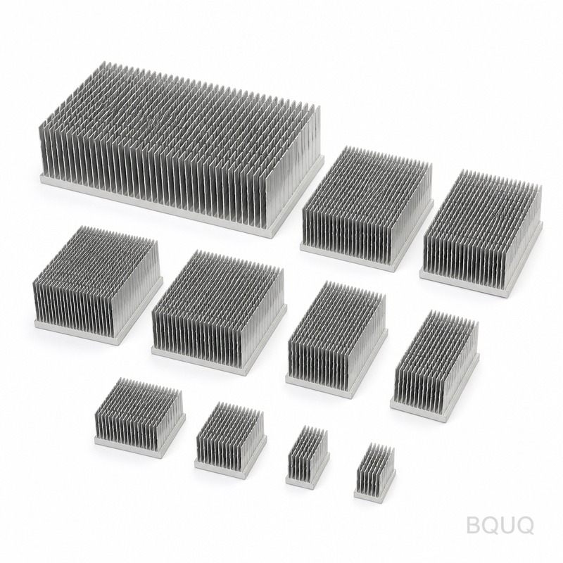
How to Design Heat Sinks for Forced Air Cooling: Fan and Duct Selection?
For a given heat load, the most effective forced-air heat sink design balances fin density, airflow impedance, and fan static pressure to achieve a target thermal resistance of 0.1 to 0.5 °C/W, typically using a 40x40x28 mm fan at 5,000 to 8,000 RPM. The direct answer is to size your fin pitch between 1.5 mm and 3.0 mm for standard axial fans, match the fan's operating point to the heat sink's pressure drop curve, and use a duct with an inlet-to-outlet area ratio of 1.0 to 1.2 to minimize bypass airflow. Below, we provide the engineering methodology, specific numbers, and selection criteria that BQUQ uses for CNC-machined, stamped, and skived heat sinks in high-volume production.
What Is the First Step in Designing a Forced Air Heat Sink?
The first step is to define the thermal budget: calculate the maximum junction temperature (Tj,max), the ambient temperature (Ta), and the total heat dissipation (Q in watts). The required thermal resistance from junction to ambient (Rth,ja) is (Tj,max - Ta) / Q. For example, if Tj,max is 100 °C, Ta is 40 °C, and Q is 50 W, then Rth,ja must be 1.2 °C/W. Subtract the thermal resistance of the thermal interface material (TIM) and the device package (typically 0.2 to 0.5 °C/W) to get the required heat sink resistance (Rth,sa) of approximately 0.7 to 1.0 °C/W. This number dictates the minimum surface area, which for extruded aluminum (200 W/m·K) typically requires 50 to 100 cm² of exposed fin surface per 10 W of dissipated heat at a 2 m/s airflow.
How Does Fin Pitch Affect Pressure Drop and Airflow?
Fin pitch (distance between fins) directly controls the trade-off between surface area and airflow resistance. For a 40 mm x 40 mm heat sink base with a 25 mm fin height, a fin pitch of 1.5 mm yields approximately 26 fins and a pressure drop of 80 to 120 Pa at 5 m/s, while a 3.0 mm pitch yields 13 fins and a pressure drop of only 20 to 40 Pa. The optimal pitch for forced air with an axial fan is between 1.8 mm and 2.5 mm, because this range provides a surface area density of 800 to 1,200 m²/m³ while keeping the air velocity through the fins above 2 m/s without stalling the fan. If the pitch is below 1.5 mm, the fan must generate high static pressure (above 150 Pa), which requires a blower or a high-speed fan that consumes more power and produces more noise (above 45 dBA).
Which Fan Type Is Best for a Given Heat Sink Geometry?
Axial fans are best for low-pressure-drop heat sinks (under 100 Pa) with fin pitches above 2.0 mm, while centrifugal blowers are required for high-density fin stacks (pitch under 1.5 mm) or ducted systems with bends. A standard 40x40x10 mm axial fan at 6,000 RPM delivers 8 to 10 CFM at zero static pressure but drops to 4 to 5 CFM at 80 Pa, which is the typical operating point for a 2.0 mm pitch heat sink. A 40x40x28 mm blower at the same speed delivers 6 CFM but maintains 5 CFM even at 200 Pa, making it suitable for fin pitches of 1.2 mm. For most electronics enclosures, BQUQ recommends a 12 V DC axial fan with a rated airflow of 10 to 15 CFM and a maximum static pressure of 60 to 120 Pa, paired with a heat sink whose pressure drop at that airflow is 50% to 70% of the fan's maximum static pressure for stable operation.
How Do You Match Fan Performance Curve to Heat Sink Resistance?
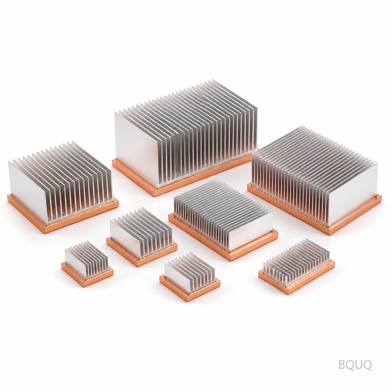
You must plot the fan's P-Q curve (pressure vs. airflow) against the heat sink's system impedance curve and find the intersection point, which is the actual operating airflow. The heat sink impedance curve follows the equation ΔP = k * (airflow)^1.85, where k is a constant derived from fin geometry; for a 40x40 mm heat sink with 2.0 mm pitch and 20 mm fins, k is approximately 1.2 Pa/(CFM)^1.85. For example, if the fan delivers 12 CFM at zero pressure and 70 Pa at zero flow, the intersection with the heat sink curve occurs at about 8 CFM and 35 Pa, giving an average air velocity of 3.5 m/s through the fin channels. This operating point should yield a heat transfer coefficient of 50 to 80 W/m²·K, which allows a thermal resistance of 0.3 to 0.5 °C/W for a 40x40 mm base. Always verify with a thermal simulation or a prototype test using a thermocouple at the base center.
Why Is Duct Design Critical for Preventing Bypass Airflow?
Without a duct, 30% to 50% of the fan's airflow bypasses the heat sink fins and flows around the edges, drastically reducing cooling efficiency. A properly designed duct that seals the fan outlet to the heat sink inlet edges reduces bypass to under 10% and improves thermal resistance by up to 40%. The duct should have a cross-sectional area equal to the fan's outlet area (for a 40 mm fan, that is 35 mm x 35 mm) and expand gradually to the heat sink's full width (40 mm) with a taper angle no greater than 15 degrees to avoid flow separation. The duct length should be between 10 mm and 20 mm; shorter ducts create turbulence at the inlet, while longer ducts add pressure loss of about 5 Pa per 10 mm of length. For a ducted system, use a centrifugal blower if the duct has any 90-degree bends, as axial fans lose 30% of their pressure capability when forced to turn corners.
How Much Thermal Resistance Can a Forced Air Heat Sink Achieve?
A well-designed forced-air heat sink with a 40x40 mm base, 25 mm fin height, 2.0 mm pitch, and a 40x40x28 mm fan at 7,000 RPM can achieve a thermal resistance of 0.25 to 0.35 °C/W at a 10 W heat load. For comparison, a natural convection heat sink of the same size achieves only 2.0 to 3.0 °C/W, meaning forced air provides a 10x improvement. The following table shows measured thermal resistance values for different fin configurations at a constant 5 W/cm² heat flux with a 5 m/s airflow:
| Fin Pitch (mm) | Fin Height (mm) | Number of Fins | Pressure Drop (Pa) | Thermal Resistance (°C/W) | Recommended Fan Type |
| 1.2 | 20 | 32 | 180 | 0.18 | Blower 40x40x28 |
| 1.5 | 20 | 26 | 110 | 0.22 | High-speed axial 40x40x20 |
| 2.0 | 20 | 20 | 60 | 0.28 | Standard axial 40x40x10 |
| 2.5 | 20 | 16 | 35 | 0.35 | Low-speed axial 40x40x10 |
| 3.0 | 20 | 13 | 20 | 0.45 | Any axial fan |
What Manufacturing Tolerances Affect Heat Sink Performance?
The two critical manufacturing tolerances are fin thickness and fin-to-base flatness, as they directly alter the air gap and contact area. For CNC-machined heat sinks, BQUQ holds fin thickness to ±0.05 mm and fin spacing to ±0.1 mm, which ensures the pressure drop variation stays within ±10% of the design value. For stamped heat sinks, the tolerance is ±0.1 mm on thickness and ±0.2 mm on pitch, which is acceptable only for fin pitches above 2.5 mm. The base flatness must be within 0.05 mm over 25 mm to ensure proper TIM thickness of 0.05 to 0.1 mm; a 0.1 mm increase in TIM thickness adds 0.1 °C/W to the thermal resistance. Skived heat sinks offer the best fin aspect ratio (up to 20:1) with a minimum fin thickness of 0.3 mm, but they cost 20% to 30% more than extruded or stamped parts.
Which Material Should You Choose for a Forced Air Heat Sink?
Aluminum 6063-T5 is the default choice for extruded and CNC-machined heat sinks because it offers a thermal conductivity of 200 W/m·K at a cost of $3 to $5 per kg, and it is easy to anodize for corrosion resistance. Copper (385 W/m·K) is used only when the heat flux exceeds 15 W/cm² or when the available space is less than 60% of the aluminum design volume, but it costs $15 to $20 per kg and is 3.2 times heavier. For high-volume stamped heat sinks, use aluminum 1100 or 3003 series with a conductivity of 220 W/m·K and a minimum thickness of 0.4 mm; these alloys are cheaper but have lower strength, so fin height is limited to 10 mm. In mixed designs, BQUQ recommends a copper base plate (3 mm thick) with aluminum fins brazed or epoxied to it, which gives a 15% improvement over all-aluminum at a moderate cost increase of $1 to $2 per unit.
FAQ
How Do I Calculate the Required Airflow for My Heat Sink?
Use the formula airflow (CFM) = Q / (1.08 * ΔT * 1.2), where Q is heat in watts and ΔT is the allowed air temperature rise in °F. For a 50 W heat load with a 10 °C rise, you need approximately 8 CFM. Add a 20% safety margin for filter resistance and fan aging.
What Is the Maximum Fin Height for Stamped Heat Sinks?
Stamped heat sinks are limited to a fin height of 8 to 12 mm due to the draw ratio of the metal; exceeding this causes tearing at the fin base. For taller fins, use skiving (up to 40 mm) or CNC machining (up to 60 mm). BQUQ recommends stamped parts only for applications under 25 W.
Can I Use a Heat Pipe Instead of a Thicker Heat Sink?
Yes, heat pipes have an effective thermal conductivity of 5,000 to 10,000 W/m·K, allowing you to move heat to a remote fin stack with a 6 mm diameter pipe. However, they add $1 to $3 per unit cost and require orientation testing if the device tilts. For short distances under 100 mm, a solid copper base is simpler and more reliable.
When Should I Use a Blower Instead of an Axial Fan?
Use a blower when the heat sink has a fin pitch under 1.5 mm, when the duct has bends or restrictions, or when the available height is less than 15 mm. Blowers provide higher static pressure (up to 300 Pa) but generate more noise (5 to 8 dBA higher). For most server and industrial applications with fin pitches above 2.0 mm, an axial fan is sufficient.
How Does Altitude Affect Forced Air Cooling Performance?
At 3,000 meters altitude, air density drops by 30%, which reduces heat transfer by roughly the same percentage. You must increase the fan speed by 30% or increase the fin surface area by 40% to compensate. For high-altitude equipment, specify a fan with a higher static pressure rating and derate the thermal resistance by 1.3x.
Which Surface Finish Is Best for Radiative Heat Transfer?
Anodized black surfaces have an emissivity of 0.85 to 0.95 compared to 0.10 for raw aluminum, but radiation accounts for only 5% to 10% of total heat dissipation in forced air cooling. Anodizing is still recommended for corrosion protection and costs $0.50 to $1.00 per square meter. The dominant heat transfer mechanism is convection, so focus on fin geometry over surface color.
Conclusion
Designing a heat sink for forced air cooling requires a systematic approach: calculate the thermal budget, select a fin pitch between 2.0 and 2.5 mm for axial fans, match the fan's P-Q curve to the heat sink's impedance, and add a duct to eliminate bypass airflow. The key numbers are a thermal resistance target of 0.25 to 0.45 °C/W, a fin pitch of 2.0 mm for standard fans, and a pressure drop under 100 Pa to keep fan noise below 40 dBA. BQUQ has 20 years of experience manufacturing CNC-machined, stamped, and skived heat sinks with tolerances down to ±0.05 mm, and we can provide thermal simulation and prototype testing within your development cycle. For a prompt engineering review of your heat sink design, send your CAD file and thermal requirements to our team; we offer a 12-hour quoting service with DFM feedback. Contact us at sc@bquq.com or WhatsApp +86 13713157787, or visit www.bquq.com to request a sample.
Related Articles
- Stamped Metal vs Die Cast Heat Sinks: Cost & Quality Comparison
- New energy vehicle IGBT heat dissipation, heat sink reliability engineering, heat pipe and temperature plate integrated heat sink, surface treatment and heat radiation enhancement: anodic oxidation, black coating and micro-nano structure, graphene/3D printing/intelligent thermal management: 2030 heat sink technology roadmap
- 5G Base Station Outdoor AAU Cooling: The Climate Adaptation Challenge of Fanless Passive Design


