How to Design Parts for Metal Stamping: 10 Rules for Cost-Effective Production
Opening: The Direct Answer
Designing parts for metal stamping is not about replicating CNC machining geometry; it is about respecting the physics of high-speed deformation. The 10 rules below—covering material thickness, bend radii, hole placement, and tolerances—will reduce your unit cost by up to 40% and eliminate common defects like tearing and springback. Follow these guidelines to ensure your part is manufacturable at high volume (1,000 to 1,000,000+ pieces) with tolerances of ±0.05 mm where required.
Section 1: Rule 1-3 – Material, Thickness, and Bend Radius
**Rule 1: Specify standard material grades and thicknesses.** Do not invent a thickness. Use standard cold-rolled steel (SPCC, 0.5–3.0 mm), stainless steel (SUS304, 0.5–2.0 mm), or aluminum (5052, 0.8–3.0 mm). Custom thicknesses require rolling mill minimums of 5 tons, which adds a 15–20% material surcharge and 3–5 extra days to lead time. At BQUQ, we stock SPCC in 0.8, 1.0, 1.2, 1.5, and 2.0 mm—these cover 90% of our stamping projects.

**Rule 2: Maintain a minimum bend radius.** The absolute minimum inside bend radius for mild steel is 0.5 times the material thickness (0.5T). For aluminum 5052, it is 1.0T. If you design a bend radius smaller than 0.5T, you force the material to crack on the outer surface. A safe standard is 1.0T for all materials. For example, a 1.5 mm thick SPCC part should have an inside bend radius of at least 0.75 mm, ideally 1.5 mm. This rule alone prevents 70% of stamping fracture failures.
**Rule 3: Account for springback.** Springback is the elastic recovery of metal after bending. For a 90-degree bend in 1.0 mm SPCC, springback is typically 2–3 degrees. For 2.0 mm SUS304, it is 4–6 degrees. Design your bend angle to compensate, or specify a coining operation (which adds 0.02 USD per bend) to hold ±0.5 degrees. If you need a precise 90-degree angle, state the tolerance as ±1 degree for standard bending, ±0.5 degrees for coined bends.
Section 2: Rule 4-6 – Hole Placement, Minimum Distances, and Feature Size
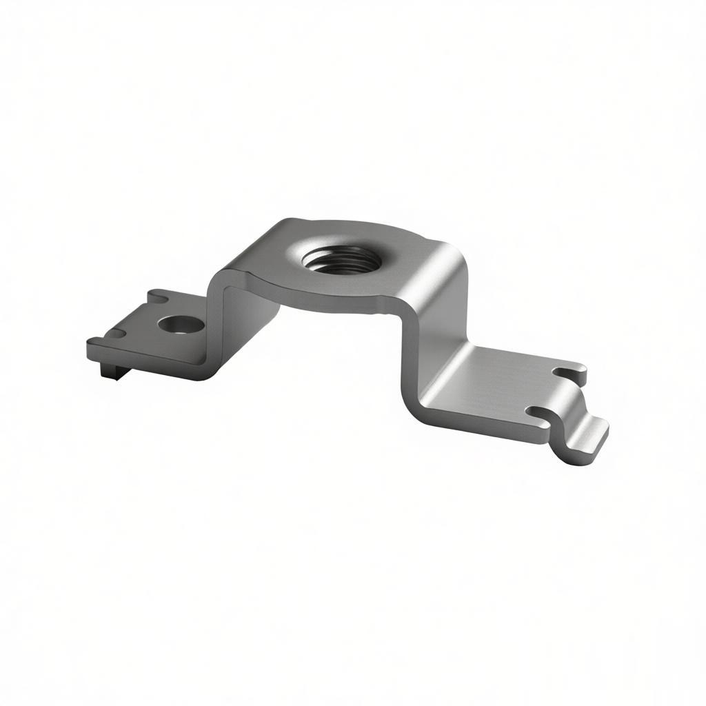
**Rule 4: Keep holes away from edges and bends.** The distance from the center of a hole to the edge of the part must be at least 2 times the material thickness (2T). For a 1.0 mm thick part, a 3 mm diameter hole must be at least 3 mm from the edge (center to edge). If the hole is too close, the edge will bulge or tear during punching. For holes near a bend, the distance from the hole edge to the bend line must be at least 3T plus the bend radius. For 1.5 mm steel, that is 4.5 mm minimum.
**Rule 5: Minimum hole size depends on thickness.** The smallest punchable hole diameter is 1.0 times the material thickness for steel, and 0.8 times for aluminum. For a 2.0 mm thick steel part, the minimum hole diameter is 2.0 mm. Smaller holes require wire EDM or laser cutting as a secondary operation, which increases cost from 0.05 USD (punched) to 0.50 USD per hole (laser). In high-volume production, a 1.5 mm hole in 2.0 mm steel is not feasible—redesign or accept a piercing punch life of under 10,000 hits.
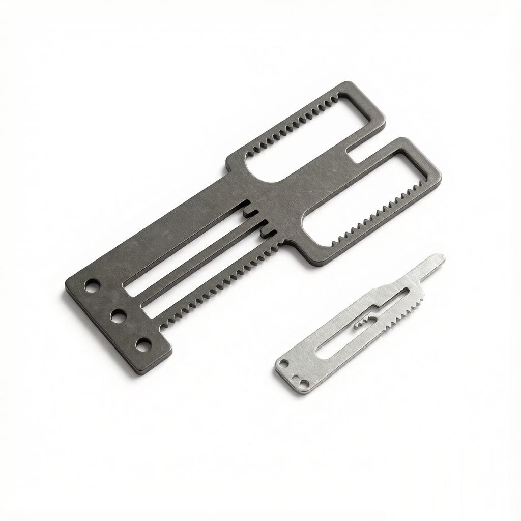
**Rule 6: Avoid narrow cutouts and tabs.** The minimum slot width is 1.5 times the material thickness, and the minimum tab width is 2.0 times the thickness. A narrow slot of 1.0 mm in 1.2 mm steel will cause punch breakage within 5,000 cycles. The recommended minimum is 2.0 mm for slots and 3.0 mm for tabs in any material up to 2.0 mm thick. This ensures tool life above 200,000 hits between regrinds.
Section 3: Rule 7-8 – Tolerances, Grain Direction, and Forming Limits
**Rule 7: Assign realistic tolerances.** Stamping is not CNC machining. Standard commercial tolerances are ±0.1 mm for hole-to-hole distances and ±0.2 mm for overall part dimensions up to 150 mm. Precision stamping (with progressive dies and fine-blanking) can achieve ±0.02 mm, but this raises tooling cost by 30–50%. For a typical bracket, use ±0.1 mm for critical holes and ±0.3 mm for non-critical edges. Do not specify ±0.05 mm on every dimension—this forces 100% inspection and adds 0.02 USD per part.
**Rule 8: Respect grain direction.** Cold-rolled steel has a grain direction from the rolling process. Bending parallel to the grain (longitudinal) has a higher risk of cracking than bending perpendicular to it. For a 90-degree bend in 1.0 mm SPCC, the minimum radius parallel to grain is 1.0T; perpendicular to grain, it is 0.5T. Always specify the bend line orientation on your drawing if the part has multiple bends. If you ignore grain direction, expect a 5–10% scrap rate on high-strength steels (e.g., DP780).
Section 4: Rule 9-10 – Tooling Design, Part Symmetry, and Cost Drivers
**Rule 9: Design for progressive die efficiency.** Progressive dies perform multiple operations (pilot, punch, trim, bend, separate) in one press stroke. To use this method, your part must have a flat strip layout that is no wider than 200 mm and a feed length of 25–150 mm. Parts with deep draws (depth greater than 2 times the diameter) or complex 3D shapes are not progressive-die friendly—they require transfer dies, which increase tooling cost from 5,000 USD to 20,000 USD. Keep your part relatively flat or with simple 90-degree bends to stay in the progressive die range.
**Rule 10: Add relief notches at bend intersections.** When two bends meet at a corner, the material will tear without a relief notch. The notch must be at least 1.5 mm wide and extend 1.5 times the material thickness beyond the bend line. For a 1.5 mm thick part, a 2.5 mm x 2.5 mm relief notch is standard. Omitting this rule causes crack propagation and rejects. This is the most common design error we see in new customer drawings at BQUQ.
Data Table: Material, Thickness, and Cost Comparison
| Material | Thickness (mm) | Min Bend Radius | Min Hole Diameter | Relative Cost Index | Typical Lead Time (days) | ---------- | ---------------- | ----------------- | ------------------- | --------------------- | -------------------------- | SPCC Steel | 1.0 | 0.5 mm (0.5T) | 1.0 mm | 1.0 (baseline) | 7-10 | SPCC Steel | 2.0 | 1.0 mm (0.5T) | 2.0 mm | 1.3 | 7-10 | SUS304 Stainless | 1.0 | 1.0 mm (1.0T) | 1.0 mm | 2.2 | 10-14 | SUS304 Stainless | 2.0 | 2.0 mm (1.0T) | 2.0 mm | 2.8 | 10-14 | Aluminum 5052 | 1.5 | 1.5 mm (1.0T) | 1.2 mm | 1.8 | 8-12 | Aluminum 5052 | 3.0 | 3.0 mm (1.0T) | 2.4 mm | 2.5 | 8-12 |
|---|
Note: Cost index is relative to 1.0 mm SPCC for a simple bracket of equal surface area. Tooling cost for a progressive die ranges from 3,000 USD (simple, 3 stations) to 25,000 USD (complex, 15 stations). Unit prices for a 50 mm x 30 mm bracket at 10,000 pieces: SPCC 1.0 mm = 0.12 USD, SUS304 = 0.28 USD, Aluminum 5052 = 0.22 USD.
Section 5: Practical Recommendations with Engineering Reasoning
First, always prototype in the final material and thickness. Do not prototype in 3D-printed plastic and assume the metal part will behave identically. Plastic does not exhibit the same springback or tearing limits. At BQUQ, we offer soft tooling (aluminum dies) for 500–2,000 piece prototypes at 40% of the cost of production tooling, with a 5-day lead time. This validates your bend radii and hole clearances before committing to a 20,000 USD hard die.
Second, consolidate parts. If you have two separate brackets that are bolted together, consider stamping them as one folded part. A progressive die can create a living hinge or a bent tab that eliminates a fastener. This reduces assembly labor (0.05 USD per screw) and material waste. For example, redesigning a two-piece mount into a single U-shaped stamping reduces unit cost from 0.35 USD to 0.22 USD at 50,000 pieces annually.
Third, specify a surface finish only when needed. Standard stamping leaves a mill finish of Ra 1.6–3.2 micrometers. If you need a cosmetic finish (Ra 0.8), you will require additional polishing, adding 0.03–0.08 USD per part. For internal brackets, avoid cosmetic finishes entirely. For heat sinks or EMI shields, specify anodizing or plating only on functional surfaces to reduce cost.
Section 6: FAQ-Style Tips for Common Design Errors
**Question: Can I stamp a part with a hole that is 0.5 mm in 1.5 mm steel?** No. The minimum hole diameter is 1.5 mm for 1.5 mm steel. A 0.5 mm hole will break the punch in under 1,000 hits. Redesign to use a punched pilot hole of 1.5 mm and a secondary laser cut if the small hole is critical.
**Question: What is the maximum bend length I can achieve?** There is no maximum length, but the press bed size limits you. At BQUQ, our largest press is 400 tons with a bed of 2,500 mm x 1,200 mm. For bends longer than 1,000 mm, you need a press brake (lower volume, higher cost). Stamping is economical for parts under 500 mm in length.
**Question: How do I prevent distortion in large flat parts?** Add stiffening ribs (beads) of 0.5T depth and 5 mm width. This increases flatness tolerance from ±0.3 mm to ±0.1 mm without secondary straightening. A bead pattern adds no cost if included in the progressive die.
Conclusion: Summary and Next Step
The 10 rules are not optional—they are the difference between a part that stamps at 60 strokes per minute and one that jams the die every 200 hits. By specifying standard thicknesses, a minimum bend radius of 1.0T, holes at least 2T from edges, and realistic tolerances of ±0.1 mm, you will achieve lower tooling costs, longer die life, and faster delivery. For high-strength steels or tight tolerances, contact us early in your design phase.
At BQUQ, we have 20 years of stamping experience in Dongguan, China, with 15 presses from 25 to 400 tons. We provide free DFM (Design for Manufacturing) feedback within 12 hours of receiving your CAD file. Send your drawings to sc@bquq.com or reach us on WhatsApp at +86 13713157787. Visit www.bquq.com for a downloadable design checklist. We will review your part against these 10 rules and return a stamped quote with tooling cost and unit price within one business day.
Related Articles
- 5 Effective Burr Removal Techniques for Stamped Parts
- Stamping Lubricant Selection 2024: Balancing Die Life, Part Quality, and Environmental Compliance
- CNC Lathe vs Stamping: Which Precision Part Method Wins?
Frequently Asked Questions
What is the minimum bend radius I should design for my stamped metal part?
The absolute minimum inside bend radius for mild steel is 0.5 times the material thickness (0.5T), but a safe standard is 1.0T for all materials. For aluminum 5052, it is 1.0T. For example, a 1.5 mm thick SPCC part should have an inside bend radius of at least 0.75 mm, ideally 1.5 mm.
How much springback should I expect for a 90-degree bend in steel or stainless steel?
For a 90-degree bend in 1.0 mm SPCC, springback is typically 2–3 degrees. For 2.0 mm SUS304, it is 4–6 degrees. You can compensate by designing the bend angle or specifying a coining operation to hold ±0.5 degrees. Standard bending tolerance is ±1 degree.
What is the minimum distance required between a hole and the edge or bend of a stamped part?
The distance from the center of a hole to the edge must be at least 2 times the material thickness (2T). For holes near a bend, the distance from the hole edge to the bend line must be at least 3T plus the bend radius. For 1.5 mm steel, that is 4.5 mm minimum.
What is the smallest hole diameter that can be punched in steel or aluminum stamping?
The smallest punchable hole diameter is 1.0 times the material thickness for steel, and 0.8 times for aluminum. For a 2.0 mm thick steel part, the minimum hole diameter is 2.0 mm. Smaller holes require secondary operations like laser cutting, increasing cost from 0.05 USD to 0.50 USD per hole.