
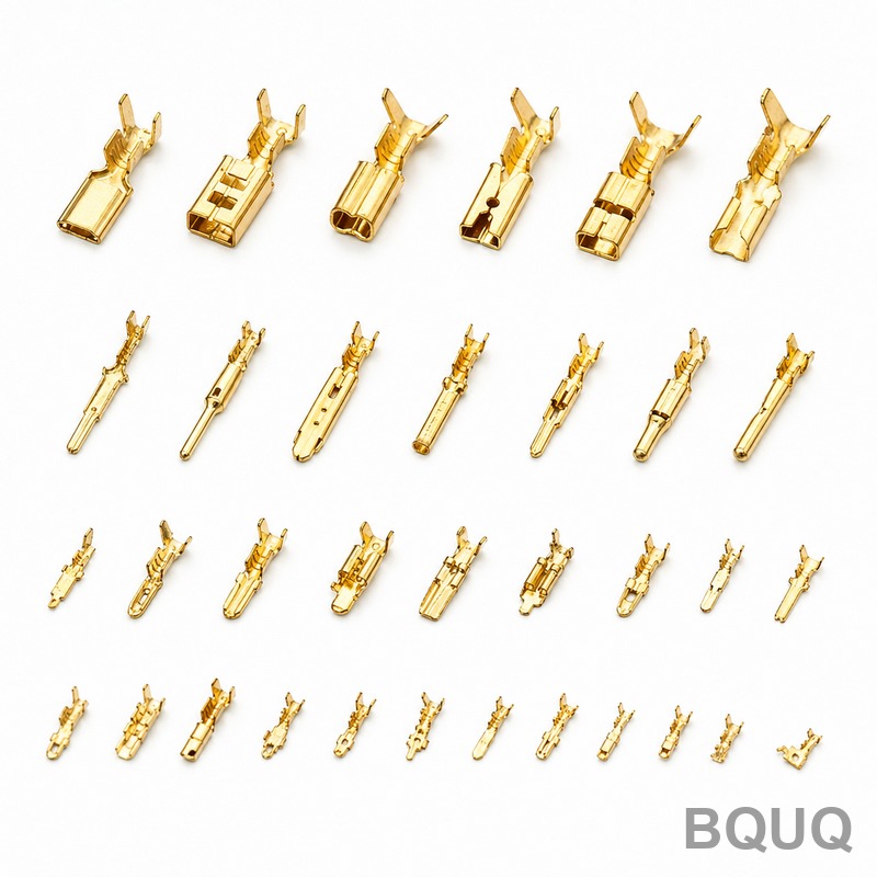
How to Inspect Stamped Parts: Key Dimensions and Quality Checks
Precision metal stamping produces high-volume components with tight tolerances, but dimensional drift, burr formation, and surface defects occur due to tool wear and material variance. A robust inspection protocol verifies critical dimensions, edge quality, and material integrity against the drawing's geometric dimensioning and tolerancing (GD&T) requirements. This article outlines the essential measurement techniques, pass/fail criteria, and statistical process control (SPC) methods used in a Tier-1 Chinese stamping facility to ensure zero-defect shipments.
Critical Dimensional Measurements for Stamped Components
The first priority in stamping inspection is verifying the three primary feature categories: hole position, bend angle, and flatness. For progressive die stampings, we measure hole center-to-center distances using a coordinate measuring machine (CMM) with a resolution of 0.001 mm. The standard tolerance for hole position is typically ±0.05 mm for automotive-grade parts, but high-speed connector parts require ±0.02 mm. Bend angles are verified with a precision protractor or optical comparator; acceptable angular deviation is ±0.5 degrees for most structural brackets. Flatness is measured on a granite surface plate using a feeler gauge; for parts under 100 mm in length, flatness must not exceed 0.10 mm total indicator reading (TIR).
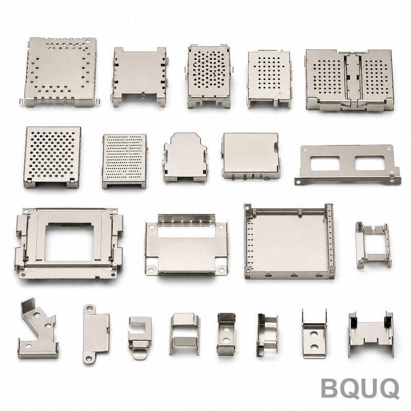
Visual and Surface Quality Inspection Parameters
Surface inspection covers burr height, scratch depth, and coating adhesion. The maximum allowable burr height for a stamped edge is 10% of the material thickness, but for critical sealing surfaces, it must be less than 0.05 mm. We use a digital microscope with 50x magnification to measure burr height and width. For material thicknesses of 1.0 mm to 3.0 mm, a burr height of 0.10 mm is accepted for non-functional edges. Scratch depth is evaluated with a profilometer; the Ra (arithmetic average roughness) value must be below 1.6 micrometers for visible surfaces. Any sign of die rollover (edge depression) that exceeds 0.15 mm is a rejection criterion, as it indicates excessive clearance in the die.
Material Hardness and Microstructure Verification
Stamped parts often require verification of material properties, especially after heat treatment or when using high-strength steels. We perform Rockwell hardness testing (HRB or HRC scale) on a sample from each production lot. For cold-rolled steel (SPCC), the expected hardness range is HRB 60-80. For stainless steel (SUS304), hardness should be HV 200-220. A metallographic cross-section is prepared every 2000 parts to check for grain flow lines; correct grain flow should follow the bend contour without cracks. If the material shows signs of work hardening beyond 15% of the original hardness value, we flag the lot for annealing or die adjustment.
Dimensional Tolerances and Go/No-Go Gauge Verification
For high-volume production, fixed go/no-go gauges provide rapid 100% inspection at the press line. We use plug gauges for hole diameters, snap gauges for external dimensions, and contour gauges for formed profiles. The tolerance class for stamped sheet metal is typically IT14 to IT16 (ISO 286), but precision parts reach IT10. For a hole with a nominal diameter of 5.00 mm, the go gauge is 5.00 mm and the no-go gauge is 5.10 mm for a general tolerance of +0.10/-0.00 mm. Every 100 parts, we cross-check the fixed gauges against a CMM to detect gauge wear; if deviation exceeds 0.005 mm, the gauge is recalibrated.
Statistical Process Control and Sampling Frequency
Inspection is not a single event but a continuous process. We follow the AQL (Acceptable Quality Limit) 0.65 sampling plan per ISO 2859-1 for visual defects, but for critical dimensions, we use variable data SPC. Every 50th part is measured on the CMM for five key characteristics: hole diameter, pitch, bend angle, flatness, and surface roughness. The control limits (UCL/LCL) are set at ±3 sigma from the process mean. If two consecutive points fall outside the control limits, the die is stopped and inspected. Our historical data shows that tool wear progresses at a rate of 0.001 mm per 10,000 strokes for a 2.0 mm thick steel die, which sets the preventive maintenance interval at 100,000 strokes.
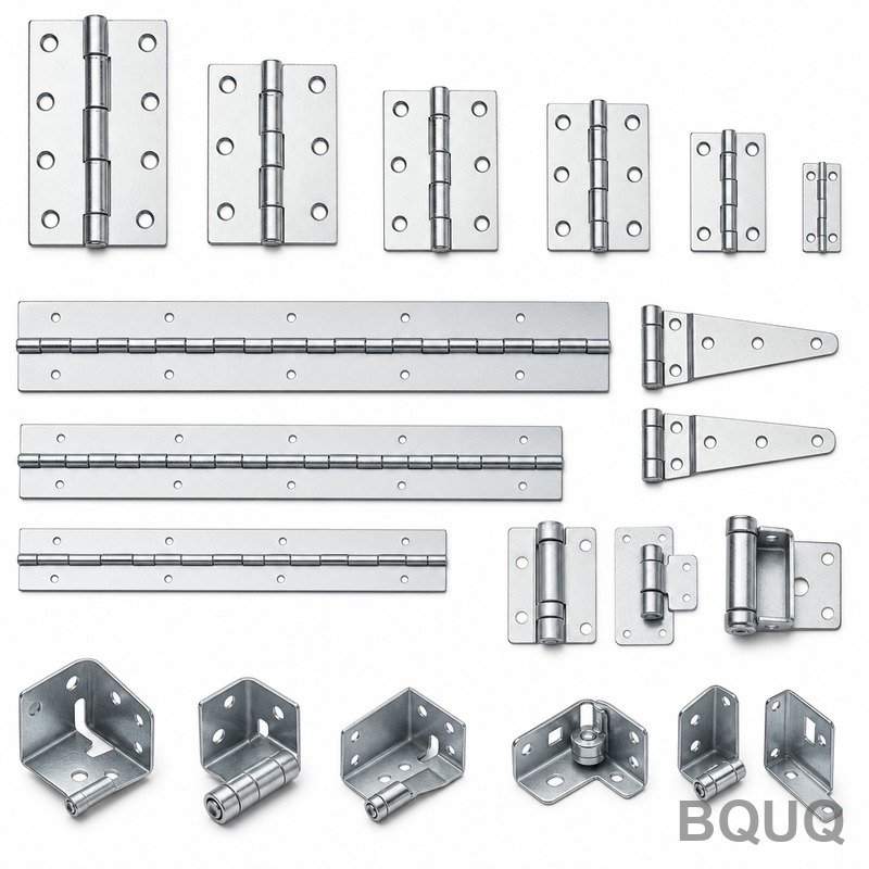
Inspection Data Table for Common Stamped Parts
| Material Thickness | Hole Position Tolerance | Bend Angle Tolerance | Max Burr Height | Flatness Limit | CMM Sampling Rate |
| 0.5 mm | ±0.03 mm | ±0.5 deg | 0.05 mm | 0.08 mm | Every 100 pcs |
| 1.0 mm | ±0.05 mm | ±0.5 deg | 0.10 mm | 0.10 mm | Every 50 pcs |
| 1.5 mm | ±0.05 mm | ±1.0 deg | 0.15 mm | 0.12 mm | Every 50 pcs |
| 2.0 mm | ±0.08 mm | ±1.0 deg | 0.20 mm | 0.15 mm | Every 30 pcs |
| 3.0 mm | ±0.10 mm | ±1.5 deg | 0.30 mm | 0.20 mm | Every 20 pcs |
Practical Tips for Inspecting Formed Features
When inspecting a bent flange, always measure the bend radius using an optical comparator rather than a caliper. A caliper will compress the material and give a false reading. For springback compensation, measure the included angle rather than the exterior angle; the die is typically over-bent by 2-3 degrees to compensate for springback in high-tensile steel. For drawn cups or deep-drawn parts, check the wall thickness distribution using an ultrasonic thickness gauge; the thinning ratio should not exceed 20% of the original blank thickness. Finally, always check the grain direction of the material against the bend line. Bending parallel to the grain direction reduces the minimum bend radius by 50% and increases crack risk.
Cost of Poor Quality and Inspection Cost Allocation
The cost of inspecting a stamped part ranges from 0.5% to 2.0% of the part's unit price, depending on the complexity and required measurement equipment. A simple bracket costing USD 0.20 per piece has an inspection cost of USD 0.001 to USD 0.004 per piece. However, the cost of a field failure is exponentially higher: a defective part in an automotive assembly line causes a line stoppage costing USD 1,500 per minute. For a stamping run of 100,000 parts, implementing a full SPC program adds approximately USD 850 in direct labor and CMM time, but it reduces the defect rate from 500 ppm to 30 ppm, saving an estimated USD 12,000 in rework and warranty claims. This justifies the investment in calibrated tooling and trained inspectors.
Conclusion and Engineering Recommendation
The most effective inspection strategy for stamped parts is a layered approach: 100% automated vision inspection for critical dimensions at the press, variable SPC sampling every 50 parts for dimensional drift, and destructive testing (hardness, tensile) every 2,000 parts. Do not rely solely on final inspection; implement in-process checks to catch tool wear early. We recommend every part be checked for burr height and hole position, as these are the two most common failure modes in stamped components. If your current supplier cannot provide a detailed inspection report with raw data, you are accepting unnecessary risk.
BQUQ operates a fully equipped metrology lab with CMM, optical projectors, and hardness testers on the factory floor in Dongguan. We provide a complete dimensional report with every shipment, including CpK values for all critical features. For a free review of your stamping drawings and a detailed inspection plan, contact our engineering team for a 12-hour quote. Email: sc@bquq.com, WhatsApp: +86 13713157787, www.bquq.com.
Related Articles
- Precision Metal Stamping: Tolerances, Materials, and Design Rules
- Intelligent online inspection and closed-loop quality control: creating a zero-defect production line for stamped parts
- Stamping digital factory and simulation-driven design: from virtual prototype to digital twin operation
Frequently Asked Questions
What are the standard tolerances for hole position in stamped parts?
Hole center-to-center distances are measured using a CMM with 0.001 mm resolution. The standard tolerance is ±0.05 mm for automotive-grade parts, while high-speed connector parts require a tighter ±0.02 mm tolerance.
What is the maximum acceptable burr height on a stamped edge?
The maximum allowable burr height is 10% of the material thickness, but for critical sealing surfaces, it must be less than 0.05 mm. For material thicknesses of 1.0 mm to 3.0 mm, a burr height of 0.10 mm is accepted on non-functional edges.
How is flatness verified for stamped parts under 100 mm in length?
Flatness is measured on a granite surface plate using a feeler gauge. For parts under 100 mm in length, flatness must not exceed 0.10 mm total indicator reading (TIR).
What hardness ranges are expected for SPCC and SUS304 materials?
For cold-rolled steel (SPCC), the expected hardness range is HRB 60-80. For stainless steel (SUS304), hardness should be HV 200-220. Hardness is verified via Rockwell testing on a sample from each production lot.


