
How to Select a Heat Sink for LED Lighting: Thermal Management Guide
The most direct answer is that you select a heat sink for LED lighting by first calculating the total thermal resistance budget (from LED junction to ambient air) and then matching that budget with a heat sink that provides the required thermal resistance (Rth) at your specified airflow and ambient temperature, typically between 0.5°C/W and 10°C/W depending on wattage. For a standard 50W LED module operating at 85°C junction temperature in a 40°C ambient, you need a heat sink with a thermal resistance of approximately 0.9°C/W or lower, which often requires a finned aluminum extrusion with a surface area of at least 400 cm². This guide provides the engineering formulas, material comparisons, and cost data you need to make that selection with confidence for your specific application.
What Is the First Step in Calculating Heat Sink Requirements for LEDs?
The first step is determining the total power dissipation (P) and the maximum allowable junction temperature (Tj) of your LED, which you get from the LED datasheet. The thermal path consists of three resistances in series: the LED junction-to-case (Rth j-c), the interface material (Rth c-s), and the heat sink-to-ambient (Rth s-a). You calculate the maximum allowable total thermal resistance (Rth total) using the formula Rth total = (Tj - Ta) / P, where Ta is the maximum ambient temperature. For example, a 100W LED with a maximum Tj of 120°C in a 50°C ambient requires a total resistance of (120-50)/100 = 0.7°C/W, leaving approximately 0.5°C/W for the heat sink after subtracting typical values for Rth j-c (0.3°C/W) and Rth c-s (0.1°C/W).
How Do You Match Heat Sink Thermal Resistance to Your LED Power?
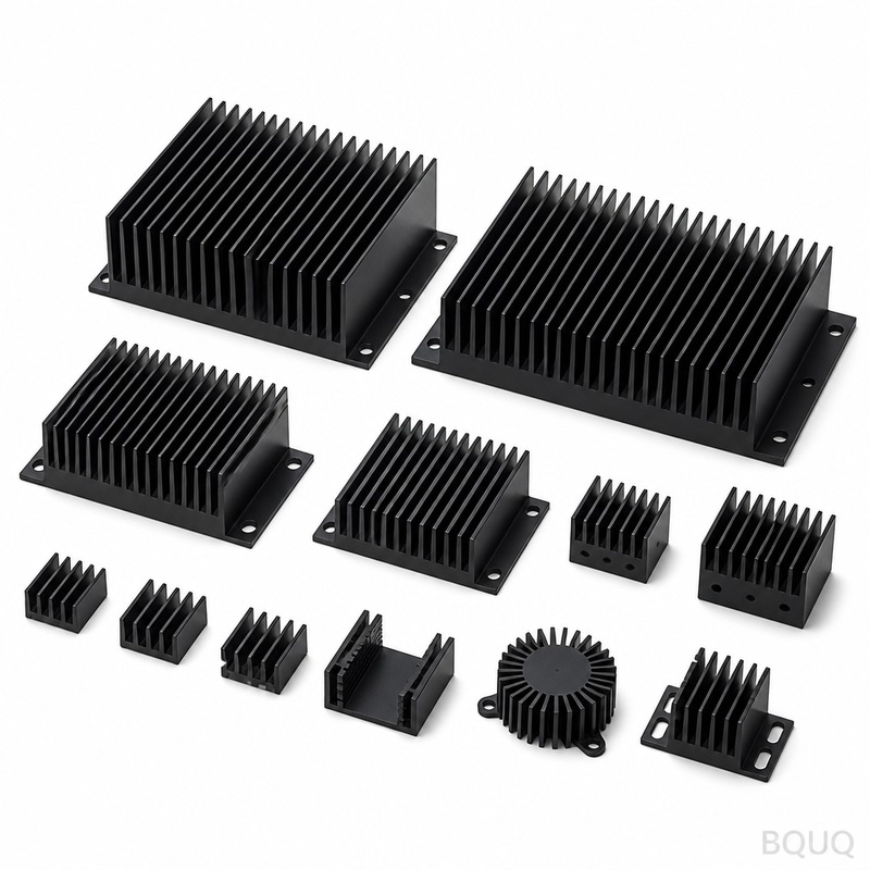
You match the heat sink's published thermal resistance (Rth s-a) to the value you calculated in the first step, but you must always derate the published value by 20-30% to account for real-world mounting conditions, dust accumulation, and orientation effects. A natural convection heat sink rated at 1.0°C/W in a lab will perform closer to 1.3°C/W in a horizontal orientation inside a sealed luminaire. For forced convection, the relationship between airflow and thermal resistance follows an exponential curve: increasing airflow from 0.5 m/s to 2 m/s typically reduces Rth by 40-50%, but beyond 3 m/s the gains diminish significantly. Use this rule of thumb: for every 10W of LED power, you need approximately 80-120 cm² of exposed fin surface area for natural convection, or 40-60 cm² for forced convection at 2 m/s airflow.
Which Heat Sink Materials Are Best for LED Thermal Management?
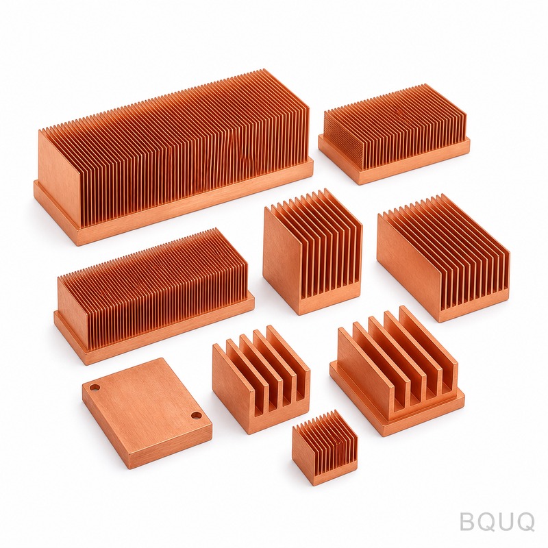
Aluminum 6063-T5 is the industry standard for LED heat sinks because it offers an excellent balance of thermal conductivity (201 W/m·K), weight, and cost at approximately $3-5 per kilogram. Copper provides 385 W/m·K thermal conductivity, which is 90% better than aluminum, but it costs $8-12 per kilogram and weighs 3.3 times more, making it practical only for high-flux applications above 200W or when space is extremely constrained. Advanced materials like graphite-based composites (500-800 W/m·K in-plane) are emerging for thin-profile LED panels, but they cost $50-100 per unit and are limited to specialized applications. For most commercial and industrial LED lighting, the recommendation is aluminum 6063-T5 with a clear anodized finish (increases emissivity from 0.09 to 0.85), which improves radiant heat transfer by up to 40%.
How Does Heat Sink Geometry Affect Cooling Performance?
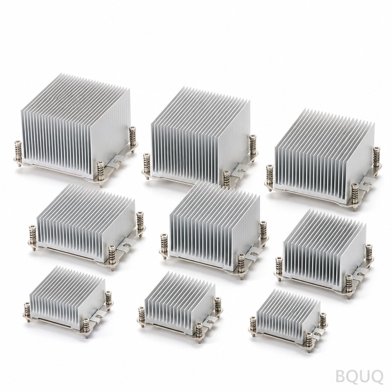
Heat sink geometry directly controls the convective surface area and airflow path, with fin spacing being the most critical parameter for natural convection. For natural convection, optimal fin spacing is 8-12 mm with fin heights of 25-50 mm and fin thickness of 2-3 mm, which allows proper air circulation through the chimney effect. For forced convection, you can reduce fin spacing to 4-6 mm and increase fin height to 60-80 mm, but this creates higher pressure drop that requires a stronger fan. Pin fin arrays outperform straight fins by 15-20% in omnidirectional airflow but cost 30-50% more to manufacture. The base plate thickness should be 5-8 mm for LED power levels below 100W, increasing to 10-15 mm for higher power to ensure proper heat spreading before the fins extract the heat.
Why Is Thermal Interface Material Critical in Heat Sink Selection?
The thermal interface material (TIM) fills microscopic air gaps between the LED module and heat sink, and selecting the wrong TIM can reduce your effective thermal performance by 30-50%. Thermal grease with a thermal conductivity of 3-5 W/m·K is the most cost-effective option at $0.10-0.30 per application, but it requires a minimum clamping pressure of 20-50 psi and can pump-out over time. Phase change materials (6-8 W/m·K) offer better long-term reliability at $0.50-1.50 per application, while thermal pads (1-3 W/m·K) are the easiest to assemble but require a 10-20% larger heat sink to compensate for their lower conductivity. For LED applications, the engineering recommendation is a phase change material for production volumes above 10,000 units per year, and thermal grease for prototyping and low-volume runs.
What Is the Actual Cost Breakdown for LED Heat Sink Manufacturing?
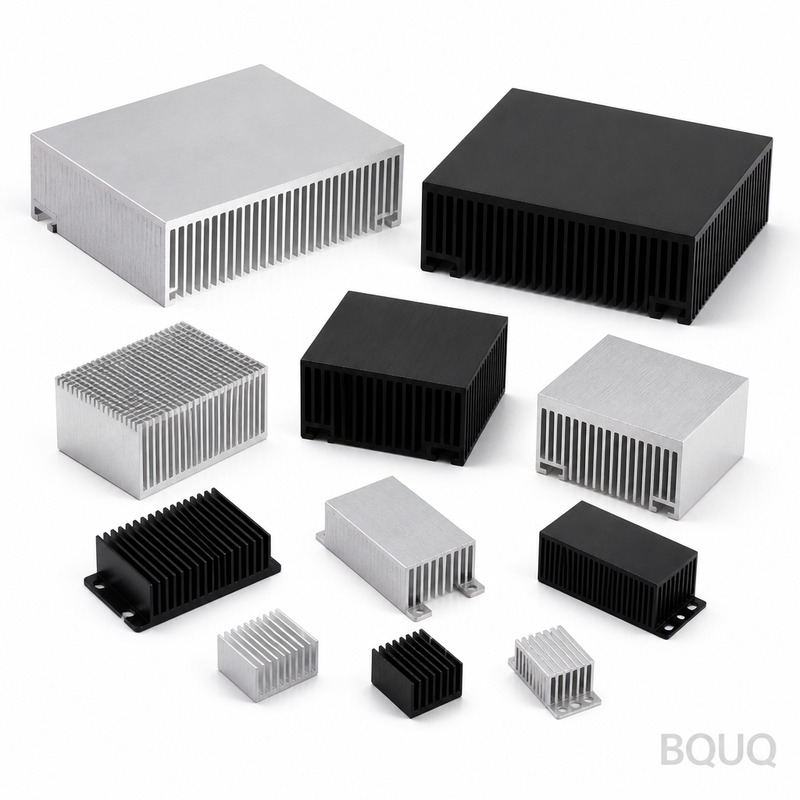
The cost of an LED heat sink depends on manufacturing method, material, and quantity, with extrusion being the dominant method for linear profiles and die-casting for complex geometries. An aluminum extrusion heat sink for a 50W LED (approximate size 200mm x 100mm x 40mm) costs between $4-8 per unit at 1,000-piece quantities, including the anodizing finish. Die-cast aluminum heat sinks for the same application cost $6-12 per unit but offer more complex fin geometries and integrated mounting features. Bonded fin heat sinks using copper or aluminum fins soldered to a base plate cost $15-30 per unit and are reserved for high-power applications above 200W or when maximum surface area is needed in a compact envelope.
| Heat Sink Type | Typical Power Range | Thermal Resistance (Rth s-a) | Unit Cost (1,000 pcs) | Lead Time |
| Aluminum Extrusion | 10-150W | 0.8-5.0 °C/W | $3-8 | 2-4 weeks |
| Die-Cast Aluminum | 20-200W | 0.6-3.0 °C/W | $6-12 | 4-6 weeks |
| Stamped/Sheet Metal | 5-30W | 2.0-8.0 °C/W | $1-3 | 1-2 weeks |
| Bonded Fin (Cu/Al) | 150-500W | 0.2-0.8 °C/W | $15-30 | 3-5 weeks |
| Forged Copper | 200-500W | 0.3-0.6 °C/W | $20-40 | 4-8 weeks |
How Do You Validate Heat Sink Performance Before Production?
You validate performance using a combination of thermal simulation (CFD) during design and physical testing on prototypes using thermocouples or infrared cameras. A CFD simulation using software like Ansys Icepak or FloTHERM can predict the heat sink's thermal resistance within +/-10% accuracy when boundary conditions are properly defined. Physical testing should follow the JEDEC JESD51-14 standard, which specifies a test setup with a heated dummy component and measurement at steady-state after 30-60 minutes. For production quality control, you should test one unit per 500 pieces using a thermal resistance tester that measures the junction temperature through the forward voltage method, which provides results within 30 seconds per unit.
When Should You Consider Active Cooling Instead of Passive Heat Sinks?
You should consider active cooling with fans or synthetic jets when the calculated heat sink volume exceeds 500 cm³ per 100W of LED power or when the available mounting area is constrained. A 100W LED in a passive configuration requires a heat sink approximately 250mm x 150mm x 60mm, while an active-cooled system with a 40mm fan at 2000 RPM can achieve the same thermal resistance in a package 50% smaller. The trade-off is reliability: a fan rated at 50,000 hours MTBF reduces the LED luminaire's effective lifespan from 100,000 hours to 50,000 hours unless redundant fans are used. For outdoor lighting where dust and moisture are concerns, passive heat sinks are strongly preferred despite their larger size, since fan failures are the leading cause of early luminaire failure.
FAQ Section
What Is the Maximum Junction Temperature for Typical LED Modules?
Most high-power LED modules have a maximum junction temperature (Tj max) of 105°C to 125°C, but operating at this limit reduces lumen output by 10-20% and can cut the LED lifetime from 100,000 hours to 30,000 hours. For every 10°C reduction in junction temperature, LED life approximately doubles. The industry best practice is to design for a junction temperature of 80-90°C to balance heat sink size, cost, and LED performance.
How Does Ambient Temperature Affect Heat Sink Selection?
Higher ambient temperatures directly reduce the temperature difference (delta T) between the heat sink and the environment, requiring a lower thermal resistance heat sink for the same LED power. For example, a heat sink rated at 1.0°C/W at 25°C ambient will need to be replaced by a 0.7°C/W heat sink for a 50°C ambient environment to maintain the same junction temperature. The rule is to always specify the maximum ambient temperature of the application, not the average, to avoid thermal runaway during summer months.
Can a Larger Heat Sink Always Solve LED Thermal Problems?
No, a larger heat sink has diminishing returns beyond a certain size because the thermal resistance of the LED junction-to-case and the interface material becomes the dominant resistance in the system. If your Rth j-c is 0.5°C/W and Rth c-s is 0.2°C/W, the heat sink can never reduce the total resistance below 0.7°C/W regardless of its size. The practical limit is that heat sinks larger than 600 cm² of surface area per 100W often show less than 10% improvement for a 50% increase in size and cost.
What Is the Difference Between Thermal Resistance and Thermal Impedance?
Thermal resistance (Rth) is a steady-state measurement in °C/W that assumes constant power, while thermal impedance (Zth) accounts for transient behavior when power is pulsed or modulated. For LED lighting with PWM dimming, thermal impedance is the more relevant parameter because the LED alternates between on and off states, causing temperature fluctuations. The heat sink's thermal mass (specific heat capacity) determines how well it smooths these fluctuations, with larger aluminum heat sinks providing better thermal buffering during PWM operation.
How Often Should LED Heat Sinks Be Cleaned or Maintained?
The cleaning frequency depends on the environment: indoor fixtures with low dust require inspection every 2 years, while outdoor fixtures or industrial environments with heavy particulates require cleaning every 3-6 months. Dust accumulation on fin surfaces can increase thermal resistance by 20-50% as it insulates the fins and blocks airflow paths. Cleaning is performed with compressed air at 30-50 psi or a soft brush, avoiding water and solvents that can damage electrical components.
Which Heat Sink Finish Provides the Best Radiative Heat Transfer?
Black anodized aluminum provides the best radiative heat transfer with an emissivity of 0.85-0.95, compared to 0.09 for raw aluminum and 0.30 for painted surfaces. The anodized layer adds 5-25 micrometers to the surface and costs approximately $0.50-1.00 per square meter of surface area. For natural convection applications, the radiative component can account for 30-40% of total heat dissipation, so anodizing is essential for passive cooling systems.
What Is the Typical Lead Time for Custom LED Heat Sink Production?
A custom aluminum extrusion heat sink has a lead time of 2-4 weeks for tooling (die cost $1,500-3,000) plus 1-2 weeks for production and anodizing. Die-cast heat sinks require 4-6 weeks for tooling (die cost $10,000-30,000) plus 2-3 weeks for production. For urgent prototyping, BQUQ can provide CNC-machined heat sinks from standard aluminum blocks in 3-5 days, allowing you to validate thermal performance before committing to production tooling.
Conclusion
Selecting the correct heat sink for LED lighting is a systematic engineering process that starts with the thermal resistance budget calculation and ends with validation testing. The key numbers to remember are the thermal resistance requirement (typically 0.5-5.0°C/W for 10-150W LEDs), the material choice (aluminum 6063-T5 for cost-effectiveness), and the derating factor of 20-30% from published values. Always specify the maximum ambient temperature and account for real-world mounting conditions to avoid premature LED failure.
For your specific LED lighting project, BQUQ provides free thermal design consultation and 3D thermal simulation within 12 hours of receiving your LED module specifications. Our 20 years of experience in CNC machining, metal stamping, and heat sink manufacturing ensures that your thermal solution is optimized for performance, cost, and manufacturability. Contact us at sc@bquq.com or WhatsApp +86 13713157787 to receive a quotation within 12 hours, or visit www.bquq.com to view our standard heat sink catalog and design guidelines.
Related Articles
- Best Copper Heat Sinks for CPU Overclocking in 2025
- Stamped Metal vs Die Cast Heat Sinks: Cost & Quality Comparison
- New energy vehicle IGBT heat dissipation, heat sink reliability engineering, heat pipe and temperature plate integrated heat sink, surface treatment and heat radiation enhancement: anodic oxidation, black coating and micro-nano structure, graphene/3D printing/intelligent thermal management: 2030 heat sink technology roadmap


