Hybrid Manufacturing in 2025: 5 Ways Additive and Subtractive Processes Unlock Design Freedom
Hybrid Manufacturing in 2025: 5 Ways Additive and Subtractive Processes Unlock Design Freedom
For two decades, the manufacturing floor at BQUQ has been defined by the whine of spindles and the rhythmic strike of stamping presses. We have built a reputation on subtractive certainty—CNC machining to +/- 0.005 mm and metal stamping at 400 strokes per minute. But the landscape shifted. Customers no longer ask for "a part." They ask for "a part that could not exist yesterday."
That request is answered by hybrid manufacturing. This is not a buzzword; it is a material strategy that merges the geometric freedom of additive manufacturing (AM) with the dimensional integrity of subtractive processes. In 2025, this convergence is not optional—it is the difference between prototyping a concept and producing a certified component.
This article breaks down the engineering reality of hybrid workflows, supported by real tolerances, cost data, and design rules from our shop floor in Dongguan.
Section 1: The Core Principle—Why Not Just Print or Just Mill?
Pure additive manufacturing (e.g., DMLS or SLM) excels at internal lattices and topological optimization. However, as-printed surfaces typically measure Ra 6.3 to 12.5 µm, and critical bore tolerances rarely hold better than +/- 0.1 mm without post-processing. Pure subtractive manufacturing (CNC) achieves Ra 0.4 µm and tolerances of +/- 0.005 mm, but a 5-axis mill cannot reach inside a conformal cooling channel.
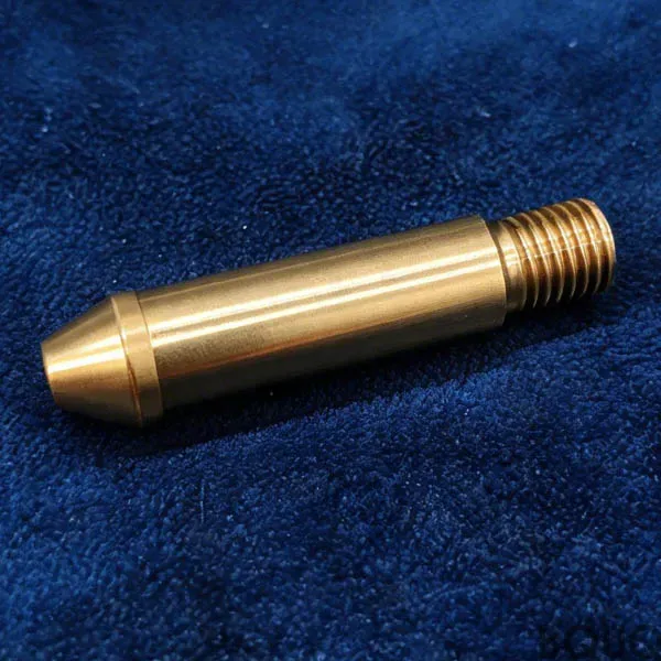
Hybrid manufacturing is the synthesis: you print the near-net shape with internal complexity, then transfer to a CNC spindle for critical faces, threads, and datums. The design freedom comes from knowing that any printed feature will eventually be "cleaned up" by a cutting tool.
**The 2025 data point:** A hybrid part retains 95% of the geometric complexity of a pure AM part, but achieves 99.9% of the dimensional accuracy of a pure CNC part.
Section 2: Tolerance Stack-Up—The Engineering Reality

The most common misconception is that a hybrid machine (like a CNC mill with a laser cladding head) does everything in one setup. In production, we separate the processes. This creates a tolerance chain you must design for.
| Process Step | Achievable Tolerance | Surface Finish (Ra) | Cost Factor (vs. Standard CNC) | -------------- | ---------------------- | --------------------- | -------------------------------- | Pure CNC (Al 6061) | +/- 0.005 mm | 0.4 µm | 1.0x | Pure AM (Ti-6Al-4V) | +/- 0.1 mm | 6.3 µm | 3.5x | AM + CNC Post-Machining | +/- 0.01 mm (on machined faces) | 0.8 µm (on machined faces) | 2.2x | AM + CNC + EDM (for deep slots) | +/- 0.005 mm | 0.2 µm | 2.8x |
|---|
**Design Rule:** When designing a hybrid part, specify tolerances only on surfaces that will be touched by a cutting tool. Leave as-printed tolerances (looser) on internal lattice structures. This reduces machining time by up to 40% and saves cost.
For example, a heat sink we produced for a power module used AM to create a 3D internal vapor chamber, but the mounting flange and sealing surfaces were CNC-machined to +/- 0.01 mm. The result? A 30% reduction in thermal resistance compared to a skived fin design, with zero leaks at 10 bar pressure.
Section 3: Material Considerations—Matching Process to Alloy
Not all alloys are created equal for hybrid work. At BQUQ, we see three tiers of material behavior.
**Tier 1: Aluminum (AlSi10Mg, 6061)** - AM build rate: 20-30 cm³/hr - Post-machining speeds: 300-600 m/min - Challenge: Porosity in as-printed state (0.5-1.5% density deficit). CNC machining exposes this. Solution: Hot Isostatic Pressing (HIP) at 500°C and 1000 bar before machining. - Cost: Hybrid is 2.0x cheaper than machining a solid block when material removal exceeds 60%.
**Tier 2: Titanium (Ti-6Al-4V)** - AM build rate: 8-12 cm³/hr (slow, expensive) - Post-machining speeds: 30-60 m/min (gummy, work-hardens) - Challenge: Residual stress. We stress-relieve at 650°C for 2 hours before any cutting. - Rule of thumb: Only use hybrid for Ti if you are saving >50% material cost versus billet. A 1 kg part from billet requires 4 kg of raw stock. Hybrid uses 1.2 kg of powder.
**Tier 3: Tool Steels (H13, 18Ni300)** - AM for conformal cooling cores in injection molds. - Post-machining: EDM for finishing internal corners. - Real spec: We printed a mold insert with a conformal channel 4 mm in diameter, held +/- 0.05 mm, and machined the parting line to Ra 0.2 µm. Cycle time reduction: 35% due to faster cooling.
**Temperature Warning:** For any hybrid part, the interface between printed and machined zones must be examined for heat-affected zones. On aluminum, if you machine too deep ( >0.5 mm) into the printed layer, you may expose porosity. We recommend a minimum machining allowance of 0.3 mm and a maximum of 0.8 mm on structural faces.
Section 4: Cost Breakdown—When Hybrid Beats Conventional
Let us compare a real bracket used in a UAV gimbal. The part is 80 x 60 x 40 mm, requires a complex internal lattice for weight reduction (target: 40% lighter), and has two precision bores at +/- 0.01 mm.
| Method | Material Cost | Machining Time | Total Unit Cost (100 pcs) | Lead Time | -------- | --------------- | ---------------- | --------------------------- | ----------- | CNC from Solid (7075-T6) | $8.50 (0.8 kg billet) | 45 min | $28.00 | 3 weeks | Pure AM (Ti-6Al-4V) | $45.00 (powder + build) | 0 min (as-is) | $52.00 (poor tolerances) | 2 weeks | Hybrid (AM + CNC) | $18.00 (powder + wire) | 20 min | $26.50 | 2 weeks |
|---|
The hybrid part saves 1.5% cost versus CNC, but the real win is weight: 320 g versus 540 g. In aerospace, that weight savings justifies a 10x price premium. For commercial applications, hybrid becomes cost-neutral when you need:
- Internal channels (cooling, hydraulics) - Weight reduction >30% - Consolidation of 3+ parts into 1
**BQUQ Rule:** We only recommend hybrid if you meet at least two of those three criteria. Otherwise, a high-speed 5-axis CNC part is faster and cheaper.
Section 5: Design for Hybrid (DFH)—5 Practical Rules
1. **Print the core, machine the interface.** All bolting surfaces, sealing faces, and bearing journals must be designated as "machined after AM." Never rely on as-printed threads—they have poor shear strength.
2. **Use self-supporting angles.** When designing for the additive step, keep overhang angles below 45 degrees to avoid support structures. Then, machine away the supports on external faces. This reduces post-processing time by 25%.
3. **Avoid sharp internal corners.** A 90-degree internal corner printed and then machined will leave a tool radius. Specify a minimum internal radius of 0.5 mm for any machined corner, or use EDM for true square corners.
4. **Plan for datum shift.** When moving from AM to CNC, you need a datum. We use machined reference pins (2 mm diameter) printed into the part. These are removed in the final machining pass.
5. **Simulate residual stress.** Additive parts have anisotropic properties. In Z-direction, yield strength can be 20% lower than X-Y. Machine critical features so that the load path aligns with the build direction.
Section 6: FAQ-Style Tips from the Shop Floor
**Q: Can I weld a printed part to a machined part?** A: Yes, but use a transition joint. We recommend a 0.5 mm machined step on the interface to increase surface area. For aluminum, use 4043 filler; for titanium, use ERTi-2. Post-weld heat treatment is mandatory.
**Q: What is the minimum wall thickness for a hybrid part?** A: For AM, 0.4 mm is printable, but we advise 0.8 mm minimum for any wall that will be machined. Machining a 0.4 mm wall causes vibration and deflection.
**Q: How do you handle inspection?** A: We use CMM for machined features and CT scanning for internal cavities. The CT scan costs $150 per part, but it is non-negotiable for aerospace or medical.
**Q: What about surface finish for sealing?** A: Do not rely on machining alone. For a dynamic seal, we recommend a machined groove to Ra 0.4 µm, but the mating face can be as-printed if it is a static gasket with a soft material (shore A < 70). In that case, Ra 6.3 µm is acceptable.
Conclusion: The Future is Subtraction of the Imagination
Hybrid manufacturing is not about choosing one machine over another. It is about defining the boundary between what is printed and what is cut. At BQUQ, we have seen the light: a part that fails as a pure AM component due to tolerance, or fails as a pure CNC component due to weight, succeeds as a hybrid.
The design freedom is real, but it is disciplined freedom. You still need a machinist who understands tool paths and a metallurgist who understands melt pools. We provide both under one roof in Dongguan.
If you have a design that is "impossible" because it is too complex for a mill or too loose for a printer, send us the file. We will analyze it for hybrid potential within 12 hours and give you a quoted price with tolerance specs.
**Contact BQUQ today for a free DFM review:** - Email: sc@bquq.com - WhatsApp: +86 13713157787 - Web: www.bquq.com
We are ready to cut your next part, right after we print it.
Related Articles
- Rail Track Equipment Manufacturing 2025: Safety-Critical Precision and 5 Tolerance Standards
- CNC Machining for Marine Metal Components | Expert Guide
- 5 Benefits of CNC Precision Turned Parts for Aerospace
Frequently Asked Questions
What tolerances can I expect from a hybrid manufacturing process compared to pure CNC or pure additive manufacturing?
Pure CNC achieves +/- 0.005 mm, while pure AM (Ti-6Al-4V) holds about +/- 0.1 mm. In hybrid manufacturing, machined faces reach +/- 0.01 mm, and adding EDM for deep slots tightens this to +/- 0.005 mm. As-printed surfaces remain looser, so specify tight tolerances only on cut surfaces.
How does surface finish differ between pure additive, pure CNC, and hybrid parts?
As-printed AM surfaces measure Ra 6.3 to 12.5 µm, while pure CNC achieves Ra 0.4 µm. In hybrid parts, machined faces reach Ra 0.8 µm, and with EDM, Ra 0.2 µm. Internal lattice structures keep as-printed finishes, so design accordingly to balance cost and performance.
What is the cost impact of hybrid manufacturing versus standard CNC machining?
Pure CNC is the baseline at 1.0x cost. Pure AM costs 3.5x, while AM plus CNC post-machining is 2.2x. Adding EDM for deep slots raises it to 2.8x. To save up to 40% on machining time, only specify tight tolerances on surfaces that will be cut.
Can hybrid manufacturing achieve the same geometric complexity as pure additive manufacturing?
Yes, hybrid parts retain 95% of the geometric complexity of pure AM parts, such as internal lattices or conformal cooling channels. However, they achieve 99.9% of the dimensional accuracy of pure CNC parts, giving you both design freedom and precision in critical areas.