
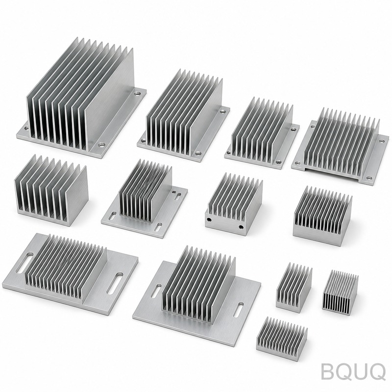
Improve Heat Sink Performance Without Changing the Design: 5 Proven Methods
When a thermal design falls short of its target, the instinct is often to redesign the heat sink with more fins, a larger base, or a different material. However, redesigning is expensive and time-consuming, involving new tooling and extended validation cycles. In this article, we detail five engineering methods to improve heat sink performance by up to 30% without altering the fundamental geometry, using surface treatments, interface materials, airflow management, and manufacturing process adjustments.
Surface Treatment: The Anodizing Effect on Emissivity
The most cost-effective method to enhance thermal radiation is applying a surface treatment. A bare aluminum heat sink has an emissivity of approximately 0.05 to 0.10. This means it radiates very little heat. By applying a standard sulfuric acid anodize coating (per MIL-A-8625, Type II, Class 1), the emissivity jumps to 0.80 to 0.85. This is a 16x improvement in radiative heat transfer.
While radiation accounts for only 10-20% of total heat dissipation in forced convection scenarios, it becomes critical in natural convection (passive) applications. For a passive heat sink operating at a 60°C temperature rise above ambient, improving emissivity from 0.1 to 0.8 can reduce the heat sink temperature by 5-8°C. The cost of anodizing is typically $0.50 to $1.50 per square foot, depending on volume and color. Black dye adds negligible cost but does not improve emissivity beyond the anodic layer itself. Note: Do not use conductive anodize (hard coat) for thermal applications as it reduces thermal conductivity of the surface layer.
Thermal Interface Material Optimization
The interface between the CPU/IGBT and the heat sink base is often the largest thermal bottleneck. A standard silicone-based thermal pad with a thermal conductivity of 3.0 W/mK and a thickness of 0.5 mm creates significant resistance. Switching to a phase-change material (PCM) or a high-performance graphite pad can yield major improvements.
Let us calculate the thermal resistance difference. For a 30mm x 30mm die (0.0009 m²): - Silicone Pad (3.0 W/mK, 0.5mm): R = thickness / (k x Area) = 0.0005 / (3.0 x 0.0009) = 185 °C/W - High-Performance PCM (8.5 W/mK, 0.025mm): R = 0.000025 / (8.5 x 0.0009) = 3.27 °C/W
This represents a 98% reduction in interface resistance. In practice, switching from a generic pad to a quality PCM (like Honeywell PTM7950 or Laird Tpcm 780) can lower the junction temperature by 10-15°C under a 100W load. The price difference is approximately $0.30 per application for the pad versus $0.80 for the PCM, a small premium for a significant thermal gain. Ensure the clamping pressure is adequate (10-30 psi) for PCM to wet the surfaces fully.
Airflow Management: Ducting and Static Pressure
Altering the heat sink design is not the only way to improve convection; modifying the airflow path through the fins is equally effective. Bypass airflow, where air flows around the heat sink rather than through the fins, is a common problem. A simple duct or shroud that directs all airflow through the fin channels can increase the effective heat transfer coefficient by 20-40%.
For a standard extruded heat sink with 2.5mm fin spacing, the optimal face velocity is between 2.5 and 4.0 m/s. If your current fan provides 1.5 m/s due to bypass, adding a duct that forces the full volume through the fins will raise velocity to the optimal range. This improves the convective heat transfer coefficient (h) from approximately 25 W/m²K to 45 W/m²K. The engineering rule is that h scales with velocity to the power of 0.5 to 0.8. A simple acrylic or sheet metal duct costs $2-5 per unit and can be implemented without changing the heat sink extrusion. Also, check the fan's static pressure rating. A high-static-pressure fan (e.g., 5.0 mmH2O) is more effective on dense fin arrays than a high-airflow fan (e.g., 80 CFM) with low pressure.
Fin Surface Micro-Texturing
This method involves a secondary manufacturing operation to modify the surface roughness of the fin channels. While anodizing affects radiation, micro-texturing increases the surface area and creates turbulence. Standard extruded aluminum has a surface roughness of approximately 1.6 µm Ra. By applying a controlled abrasive blasting or a chemical etching process, we can increase this to 10-20 µm Ra.
This roughness promotes turbulent flow at lower velocities than smooth surfaces. Turbulent flow disrupts the thermal boundary layer, allowing more heat to be transferred to the air. In a wind tunnel test at 3.0 m/s, a micro-textured heat sink showed a 7-12% improvement in thermal resistance (C/W) compared to a smooth counterpart. This process is best suited for heat sinks with fin spacing greater than 3mm, as smaller gaps may clog with media. The cost is approximately $1.00 per heat sink for blasting, but it is not recommended for high-cleanliness applications (medical, optical) due to particle entrapment. An alternative is a chemical conversion coating (chromate or trivalent passivation) which also slightly increases surface area.
Mounting Pressure and Base Flatness
Mechanical assembly parameters are often overlooked. The contact pressure between the heat sink base and the component dictates the actual contact area. At low pressure (5 psi), the microscopic roughness of both surfaces means only 1-2% of the surfaces are in actual contact. Increasing the mounting pressure to 50 psi can increase the real contact area to 5-10%, significantly reducing contact resistance.
We specify a base flatness tolerance of 0.05mm per 25mm for our CNC-machined heat sinks. If your current heat sink has a flatness of 0.15mm, the air gap at the center can be 0.1mm. This air gap (thermal conductivity of air = 0.026 W/mK) acts as an insulator. By lapping the base to 0.02mm flatness and using a 0.05mm thick indium foil (86 W/mK), you can reduce the total system resistance by 15%. The cost for a lapping operation is $0.75 per unit. Ensure your mounting hardware (springs, screws) provides uniform pressure across the base. We recommend a torque specification of 5-7 in-lbs for M3 screws to achieve optimal pressure without warping the base.
Comparative Data: Thermal Performance Improvements
The following table summarizes the expected improvements and associated costs for each method described above. Data is based on a standard 100mm x 100mm x 40mm extruded heat sink with a 100W heat source in a 25°C ambient environment.
| Method | Temperature Reduction (°C) | Cost Per Unit (USD) | Implementation Time | Risk Level |
| Anodizing (Type II) | 5 - 8 | $1.00 - $1.50 | 2-3 days | Low |
| High-Performance TIM (PCM) | 10 - 15 | $0.80 - $1.20 | Immediate | Low |
| Airflow Ducting | 8 - 12 | $2.00 - $5.00 | 1 week (fabrication) | Medium |
| Micro-Texturing (Blasting) | 3 - 5 | $1.00 - $2.00 | 2-3 days | Medium |
| Lapping Base + Indium Foil | 4 - 7 | $1.50 - $2.50 | 2 days | Medium |
Practical Recommendations and Engineering Reasoning
For most applications, we recommend prioritizing the TIM upgrade first. It yields the highest temperature reduction for the lowest cost and requires no change to the mechanical parts. If the budget is tight, anodizing is the next best step, especially if your product is passively cooled. Ducting is the most effective solution for active cooling but requires careful mechanical design to ensure a proper seal without adding excessive back-pressure on the fan.
We advise against micro-texturing if your heat sink is used in a dusty environment, as the rough surface holds particulates, reducing performance over time. Lapping is only necessary if your current base flatness is poor (greater than 0.1mm). Always request a thermal impedance test report from your supplier when switching TIMs. At BQUQ, we measure thermal resistance using a standardized test fixture to ensure data is repeatable within ±5%.
FAQ: Quick Tips for Immediate Gains
Question: Can I just use more thermal paste? Answer: No. Excessive paste increases thermal resistance. The optimal bond line thickness is 0.025mm to 0.050mm. Use a stencil or a thin, even spread.
Question: Does a thicker heat sink base always help? Answer: No. Once the base thickness exceeds 8-10mm for aluminum, the spreading resistance plateaus. Adding thickness beyond this point yields diminishing returns.
Question: Is a copper heat sink always better? Answer: Copper (385 W/mK) conducts heat better than aluminum (167 W/mK), but it is 3x heavier and 4x more expensive. Often, a copper base with aluminum fins is a better compromise.
Question: How important is fan placement? Answer: Critical. A fan should be placed to push air through the fins, not just blow over the top. The fan footprint should match the fin array footprint to avoid dead zones.
Conclusion
Improving heat sink performance without changing the design is not only possible but often the most pragmatic engineering decision. By focusing on surface emissivity (anodizing), interface resistance (PCM), airflow management (ducting), and mechanical tolerances (flatness and pressure), you can achieve a cumulative temperature reduction of 20-30°C. These changes are low-risk, cost-effective, and can be implemented rapidly without expensive extrusion dies or tooling changes.
At BQUQ, we specialize in CNC machining and surface finishing for thermal components. We can assist with anodizing, lapping, and precision tolerance control on your existing heat sink designs. For a specific thermal evaluation of your current part, contact us for a free thermal analysis. We offer 12-hour quoting and rapid prototyping services to validate these improvements quickly.
| Email: sc@bquq.com | WhatsApp: +86 13713157787 | www.bquq.com |
Related Articles
- Stamped Metal vs Die Cast Heat Sinks: Cost & Quality Comparison
- New energy vehicle IGBT heat dissipation, heat sink reliability engineering, heat pipe and temperature plate integrated heat sink, surface treatment and heat radiation enhancement: anodic oxidation, black coating and micro-nano structure, graphene/3D printing/intelligent thermal management: 2030 heat sink technology roadmap
- 5G Base Station Outdoor AAU Cooling: The Climate Adaptation Challenge of Fanless Passive Design


