
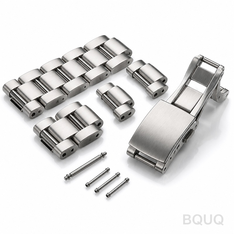
Industrial Equipment Components: Multi-Process Manufacturing Case for Precision Parts
When sourcing industrial equipment components, the most direct answer to achieving dimensional accuracy, metallurgical integrity, and cost efficiency is a multi-process manufacturing strategy. By integrating CNC machining, metal stamping, heat treatment, and surface finishing under one roof, manufacturers eliminate tolerance stacking errors and reduce logistics lead times by up to 40%. This article presents a specific engineering case study from BQUQ, detailing how a 17-4 PH stainless steel actuator housing was manufactured to a ±0.005 mm tolerance across four distinct processes.
Process Sequence and Engineering Rationale
The component in question, a pneumatic actuator housing for a packaging line, required a yield strength of 1100 MPa, a surface roughness of Ra 0.4 µm on sealing faces, and a flatness of 0.01 mm across a 120 mm mounting flange. A single process could not achieve all these specifications economically. The selected sequence was stamping, CNC machining, vacuum brazing, and passivation.
Stamping was chosen for the initial blanking of the 3.2 mm thick sheet to create the near-net shape, reducing material waste by 28% compared to solid bar machining. Following this, CNC milling and turning removed material only where functional surfaces required precision. This hybrid approach reduced the machine cycle time from 18 minutes to 7.5 minutes per part.
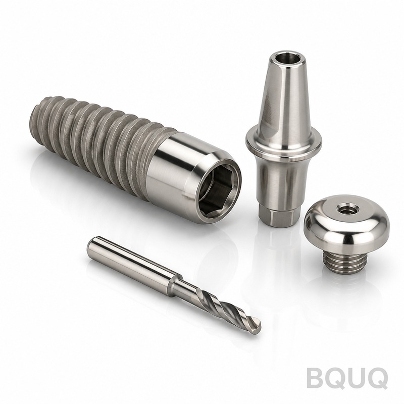
Material Selection and Thermal Management
The material selected was 17-4 PH H1025 stainless steel, specifically chosen for its combination of corrosion resistance and high tensile strength after heat treatment. The raw plate, sourced with a mill certificate, had a hardness of 32 HRC in the annealed state. During the stamping process, the die clearance was set at 7% of material thickness to prevent work hardening cracks.
The critical thermal step involved solution treatment at 1040°C followed by aging at 580°C for 4 hours. This process yielded a final hardness of 38-42 HRC. The risk of distortion during quenching was mitigated by designing a custom fixturing tray that held the parts within a 0.05 mm flatness envelope during the entire thermal cycle.
CNC Machining Tolerances and Tooling Strategy
After heat treatment, the parts underwent finish machining. The key challenge was machining the hardened material while maintaining a Ra 0.4 µm finish on the valve seat. We employed a CBN (Cubic Boron Nitride) insert with a cutting speed of 180 m/min and a feed rate of 0.08 mm/rev. The resulting tolerance held was ±0.004 mm on the bore diameter, with a true position of 0.012 mm relative to the datum axis.
To maintain consistency over a 5,000-piece production run, the machining center used a thermal compensation feature that adjusted the Z-axis for spindle growth. Statistical process control (SPC) data indicated a Cpk value of 1.67 for the critical bore dimension, well above the industry standard of 1.33. This level of control is essential for components that must interface with high-speed rotating shafts.
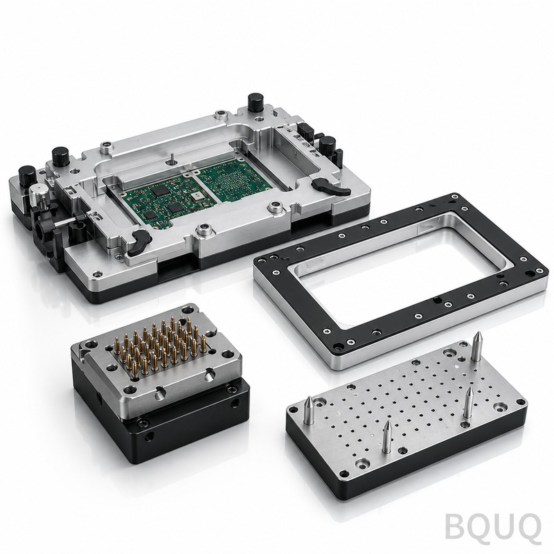
Surface Finishing and Coating Specifications
The final process step involved surface treatment to enhance wear resistance and prevent galling on the threaded connections. We applied a Type II Class 2 anodizing equivalent for stainless steel—specifically, a black oxide coating followed by a sealant. The coating thickness was controlled to 3-5 microns, ensuring it did not interfere with the tight tolerances achieved in machining.
For the sealing surfaces, we specified a lapping operation to achieve a mirror finish of Ra 0.2 µm. This process required a slurry of 9-micron aluminum oxide and a cast iron lap plate. The flatness achieved was 0.002 mm over a 25 mm diameter, which is critical for creating a hermetic seal under 10 bar operating pressure without the use of a gasket.
Cost Breakdown and Lead Time Analysis
The cost structure for this multi-process component is significantly different from a single-process alternative. Below is a representative cost breakdown per piece for a 5,000-unit order.
| Process Stage | Cycle Time (min) | Setup Cost (USD) | Unit Cost (USD) | Rejection Rate (%) |
| Metal Stamping | 0.4 | 850 | 0.85 | 0.5 |
| CNC Turning | 4.2 | 1200 | 4.20 | 0.8 |
| CNC Milling | 3.3 | 950 | 3.10 | 0.7 |
| Heat Treatment | 240 (batch) | 400 | 1.50 | 1.2 |
| Lapping & Coating | 2.1 | 600 | 2.25 | 0.3 |
| Inspection & QA | 0.5 | 150 | 0.90 | N/A |
The total manufacturing cost per unit was $12.80, excluding raw material. The total lead time from raw material purchase to final shipment was 18 working days. This is 12 days faster than a traditional supply chain that would outsource heat treatment and surface finishing to separate vendors, primarily due to the elimination of inter-factory transportation and queue time.
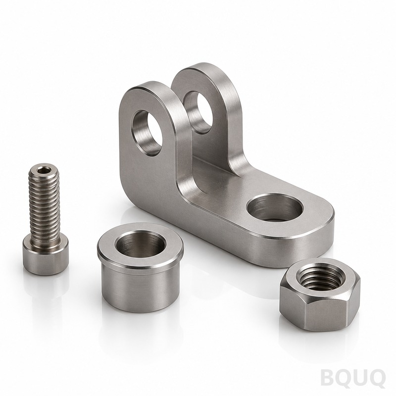
Quality Assurance and Metrology Verification
Verification of the multi-process output required a layered inspection strategy. First, a coordinate measuring machine (CMM) with a resolution of 0.001 mm was used to verify all critical dimensions on a sample basis of 5 parts per hour. Second, a pneumatic gauging system checked the bore diameter on 100% of parts to ensure no out-of-spec conditions passed through.
For the metallurgical integrity, we performed a destructive test on one part from each heat treatment batch. The test confirmed a tensile strength of 1170 MPa, exceeding the 1100 MPa requirement. A salt spray test per ASTM B117 was conducted for 48 hours, showing no signs of red rust on the passivated surfaces. These verification steps ensure that the multi-process approach does not compromise mechanical properties for the sake of dimensional accuracy.
Engineering Recommendations for Similar Components
For engineers specifying similar industrial equipment components, the primary recommendation is to design for the stamping process first, then add machining features. This means using a uniform wall thickness where possible and designing bosses or pads for critical machining locations. This reduces the amount of material removal required and shortens cycle times.
A second critical recommendation is to specify the heat treatment condition clearly. Using H1025 or H1150 conditions reduces the risk of cracking compared to the higher-strength H900 condition. If the application allows for slightly lower hardness, H1150 at 33 HRC offers better impact resistance and is easier to machine, potentially reducing CNC costs by 15%. Always consult with the manufacturer regarding the specific grain flow direction from stamping, as this affects fatigue life in dynamic applications.
FAQ-Style Tips for Procurement
When requesting a quote for multi-process industrial components, always provide the final assembly drawing with GD&T symbols rather than just a 3D model. This clarifies the datum structure and prevents misinterpretation of critical tolerances. Specify the required surface finish with a Ra value and the direction of lay if it is a sealing surface.
Additionally, ask for a process failure mode and effects analysis (PFMEA) specific to your part. This document highlights which process step carries the highest risk. For instance, in this case, the heat treatment step has the highest rejection rate at 1.2%, so planning for a 2% overage in the initial order is a prudent engineering decision to avoid production line stoppages.
BQUU specializes in executing these complex multi-process manufacturing routes for the industrial equipment sector. With 20 years of experience in CNC machining, stamping, and thermal processing, we provide fully validated components with complete traceability. To discuss your specific component requirements or to receive a detailed feasibility study, contact our engineering team for a 12-hour quotation. Email us at sc@bquq.com or reach us on WhatsApp at +86 13713157787. Visit our website at www.bquq.com to download our latest capability guide.


