
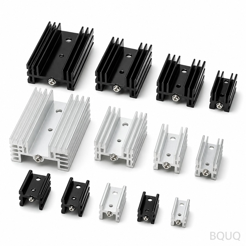
LED Heat Sink Design: Why Thermal Management Determines LED Lifespan and Performance
The direct answer is that LED lifespan is exponentially tied to junction temperature; a mere 10°C increase above the recommended operating point can halve the useful life of the chip. Thermal management, primarily through proper heat sink design, is not an accessory but the primary determinant of whether an LED system lasts 50,000 hours or fails at 15,000 hours. This article provides the engineering data and design rules necessary to ensure your LED thermal solution meets its lifetime specification.
The Physics of LED Degradation: The Arrhenius Equation in Practice
LEDs do not typically "burn out" like incandescent bulbs; they experience lumen depreciation and catastrophic failure due to accelerated chemical reactions within the phosphor and semiconductor junction. The industry standard for predicting this is the Arrhenius equation, which models how reaction rates increase with temperature.
For a typical mid-power LED (e.g., 3030 or 5630 package) operating at a junction temperature (Tj) of 85°C, the expected L70 lifespan (time to reach 70% of initial lumen output) is approximately 50,000 hours. However, if the heat sink is undersized and allows Tj to rise to 105°C, the L70 lifespan drops to approximately 20,000 hours. This is a 60% reduction in service life caused by a single 20°C delta. For high-power COB (Chip on Board) LEDs running at 120°C, the failure rate increases by a factor of 3.2 compared to operation at 90°C, according to accelerated life test data published by major LED manufacturers like Cree and Lumileds.
The critical metric is **Thermal Resistance (Rth)** , measured in °C/W. This value defines the temperature rise per watt of heat dissipated. A heat sink with a thermal resistance of 1.0 °C/W will rise 30°C above ambient when dissipating 30W of heat. The design goal is to minimize total Rth from the junction to ambient (Rth j-a) to maintain Tj below the manufacturer's maximum rating, typically 105°C to 125°C, while aiming for an optimal operating range of 70°C to 85°C for maximum efficacy and lifespan.
Aluminum vs. Copper: Material Selection and Cost Analysis
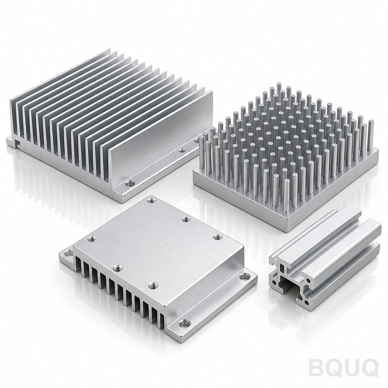
The choice of heat sink material is a balance between thermal conductivity, weight, and cost. Aluminum 6063-T5 is the industry standard for extruded heat sinks due to its excellent balance of properties and cost. Copper offers roughly 1.6 times the thermal conductivity of aluminum but is 3.3 times heavier and significantly more expensive.
For LED applications, the thermal interface material (TIM) and the heat sink base thickness are often more critical than the bulk material. A 2.0mm thick aluminum base plate will spread heat adequately for most mid-power arrays. However, for high-flux density COB LEDs, a 4.0mm thick copper base plate or a vapor chamber may be required to prevent "hot spots" directly under the die.
| Material | Thermal Conductivity (W/m·K) | Density (g/cm³) | Relative Cost Index | Typical Application |
| Cell1 | Cell2 | Cell3 | Cell4 | Cell5 |
| Aluminum 6063-T5 | 201 | 2.70 | 1.0 | Extruded fins, standard housings |
| ADC-12 Die Cast Aluminum | 96 | 2.71 | 0.8 | Complex geometries, mass production |
| C1100 Copper | 398 | 8.96 | 4.2 | High-power COB, localized heat spreading |
| Aluminum 1050 (Sheet) | 222 | 2.71 | 1.1 | Stamped heat sinks, low profile |
**Cost Breakdown:** For a typical 50W LED floodlight, an extruded aluminum heat sink (approx. 150g) costs approximately USD 3.50 to 4.50 per unit in quantities of 5,000. A die-cast alternative costs USD 2.80 to 3.50 but offers 10-15% worse thermal performance. A copper insert solution costs USD 5.20 but can reduce Tj by 8°C, extending lifespan from 35,000 to 60,000 hours, which may justify the cost for premium lighting products.
Heat Sink Geometry: Fin Density, Height, and Orientation
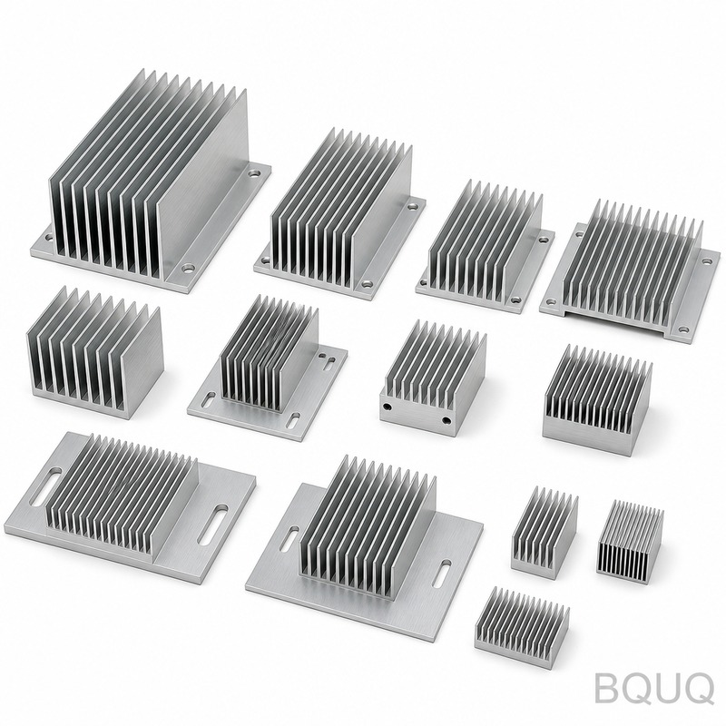
The geometric design of the fins determines the convective heat transfer coefficient (h). For natural convection (passive cooling), the optimal fin spacing is typically between 6mm and 12mm. Fins spaced too tightly restrict airflow; fins spaced too widely reduce the total surface area.
For a vertical fin heat sink operating in still air, a fin height of 40mm with a thickness of 1.8mm and a pitch of 8mm yields a surface area of approximately 0.45 m² per 100mm of length. This configuration can dissipate roughly 30W with a 15°C temperature rise above ambient. If the fins are shortened to 20mm, the surface area drops to 0.25 m², and the same heat load produces a 28°C rise, significantly reducing LED lifespan.
**Orientation is critical.** A heat sink designed for vertical fin orientation will lose 20-30% of its dissipation capacity if mounted horizontally with fins facing downward due to the suppression of natural convection plumes. For outdoor fixtures, this must be considered in the design phase. For forced convection (active cooling), fin spacing can be reduced to 3-4mm, and the airflow velocity (typically 2-3 m/s) increases the heat transfer coefficient by 3 to 5 times, allowing for 50-70% reduction in heat sink volume.
Surface Treatment and Emissivity: The Role of Anodizing
While conduction and convection are primary, radiation accounts for 15-30% of total heat dissipation in natural convection systems. A bare aluminum surface has an emissivity of only 0.05 to 0.10, meaning it radiates almost no heat. Black anodizing increases emissivity to 0.85 to 0.95, dramatically improving radiative heat transfer.
For a heat sink operating at 70°C in a 25°C ambient, the radiative heat loss from a black anodized surface is approximately 450 W/m². The same surface bare aluminum radiates only 30 W/m². This means for the same size heat sink, anodizing can reduce the overall thermal resistance (Rth) by 10-15%. The anodizing layer is also electrically insulating, which is beneficial for LED modules that require electrical isolation from the heat sink (though dielectric breakdown voltage of standard anodize is 500V per 25 microns, so specify 50 microns minimum for mains-isolated designs).
**Specification:** BQUQ standard anodizing is sulfuric acid anodize, 18-25 microns thickness, clear or black, per MIL-A-8625 Type II standards. Tolerances on the anodize layer are +/- 5 microns, which does not affect the mounting tolerances of the LED.
Real-World Data: Thermal Resistance and Lifespan Comparison
The following table compares three heat sink designs for a 100W equivalent LED streetlight module (actual LED power: 30W). The target is to keep Tj below 85°C for a 50,000-hour L70 rating at 25°C ambient.
| Design Type | Heat Sink Weight (g) | Rth j-a (°C/W) | Tj at 30W (Ambient 25°C) | Estimated L70 Lifespan (Hours) | Unit Cost (USD) |
| Cell1 | Cell2 | Cell3 | Cell4 | Cell5 | Cell6 |
| Undersized Extrusion | 300 | 3.5 | 130°C | 12,000 | 2.10 |
| Standard Extrusion | 650 | 2.0 | 85°C | 50,000 | 4.20 |
| High-Performance Die-Cast | 720 | 1.5 | 70°C | 70,000+ | 5.80 |
The data demonstrates that spending an additional USD 2.10 per unit for a properly sized heat sink (moving from 300g to 650g) increases lifespan by 38,000 hours. In a commercial application, this reduces replacement labor costs and warranty claims. The high-performance die-cast option, while more expensive, allows for operation in higher ambient temperatures (up to 40°C) while still maintaining Tj below 85°C.
FAQ-Style Design Tips and Common Pitfalls
**Q: Is it better to have a larger heat sink or a fan?** A: For lifespan-critical applications, use passive cooling. Fans have a MTBF of only 30,000 to 50,000 hours and introduce failure points, noise, and dust accumulation. A passive heat sink sized for 25°C ambient will last the life of the LED. Only use forced air if size constraints are absolute, and design for fan redundancy.
**Q: What is the acceptable temperature for the heat sink surface?** A: The heat sink surface temperature will be 20-30°C lower than the junction temperature. For a Tj of 85°C, the heat sink near the LED will measure approximately 60-65°C. This is safe to touch but indicates the system is working near the upper limit. If the heat sink surface exceeds 75°C, you are likely overheating the LED.
**Q: Should I use thermal paste or a thermal pad?** A: For production, a high-quality thermal pad (e.g., 1.0 W/m·K) is recommended for ease of assembly and consistency. Thermal paste (3.0-6.0 W/m·K) is better thermally but requires precise application and can "pump out" over thermal cycling. Ensure the mounting pressure is between 20-30 PSI for pads to achieve optimal contact.
**Q: How do I calculate the required heat sink size?** A: Use the formula: Rth required = (Tj max - T ambient max) / LED Power (W). For a 30W LED with a max Tj of 105°C and a max ambient of 40°C, the required Rth is (105-40)/30 = 2.16 °C/W. Choose a heat sink with an Rth of 2.0 °C/W or lower to include a safety margin.
Conclusion and Manufacturing Considerations
Thermal management is the most critical factor in LED reliability. Ignoring heat sink design leads to premature failure, color shift, and lost revenue. The engineering data is clear: maintaining a junction temperature below 85°C is the benchmark for achieving a 50,000-hour lifespan. Material selection, fin geometry, and surface treatment are all levers that the design engineer must pull to optimize for cost and performance.
At BQUQ, we have 20 years of experience in CNC machining, metal stamping, and heat sink manufacturing. We understand that a thermal solution is only as good as its manufacturing tolerances. Our processes hold heat sink base flatness to 0.05mm over 100mm to ensure minimal thermal interface resistance. We offer precision machining for mounting holes within +/-0.02mm, and our anodizing lines provide consistent thickness for reliable electrical isolation.
If you are in the design phase and need a thermal simulation or a prototype heat sink, we can provide engineering feedback and a quote within 12 hours. Send your CAD files or thermal requirements to our engineering team for a manufacturing feasibility and cost analysis.
Email: sc@bquq.com WhatsApp: +86 13713157787 www.bquq.com


