
LED Heat Sink Design: Why Thermal Management Determines LED Lifespan and Performance
The direct answer is that LED lifespan is fundamentally a function of junction temperature (Tj). For every 10°C increase above the rated maximum junction temperature, the LED’s useful life is reduced by approximately 50%, a rule known as the Arrhenius equation. Proper heat sink design ensures the junction temperature stays below 85°C for standard LEDs and below 105°C for high-power variants, which directly translates to a rated lifespan of 50,000 to 100,000 hours instead of premature failure at 10,000 hours.
The Thermal Failure Mechanism in LED Packages
LEDs are highly efficient at converting electricity to light, but they are not perfect. A typical high-power LED (e.g., Cree XP-L or Lumileds Luxeon) converts only 30-40% of input electrical power into visible light. The remaining 60-70% is dissipated as heat. For a 10W LED, this means 6-7W of heat must be conducted away from the semiconductor junction. Without a heat sink, the junction temperature will exceed 150°C within seconds, causing immediate spectral shift, lumen depreciation, and eventual catastrophic failure.
The thermal path in an LED system is a series of resistances: junction-to-case (Rθjc), case-to-solder point (Rθcs), and solder point-to-ambient (Rθsa). The heat sink addresses the final resistance (Rθsa), which typically accounts for 70-80% of the total thermal resistance in a poorly designed system. A well-designed heat sink can reduce Rθsa from 15°C/W to under 3°C/W for a 10W LED, keeping Tj below 85°C at 25°C ambient.
Material Selection: Aluminum vs. Copper vs. Composite
The choice of heat sink material is the first critical design decision. The table below compares the three most common materials used in LED thermal management for CNC-machined and stamped heat sinks.
| Material | Thermal Conductivity (W/m·K) | Density (g/cm³) | Relative Cost per kg | Typical Application |
| 6063-T5 Aluminum | 201 | 2.70 | 1.0x | Standard LED fixtures up to 50W |
| 6061-T6 Aluminum | 167 | 2.70 | 1.1x | CNC-machined housings, structural parts |
| C1100 Copper | 398 | 8.96 | 4.5x | High-flux COB LEDs, compact modules |
| Die-Cast ADC12 | 96 | 2.68 | 0.8x | Mass-produced consumer fixtures |
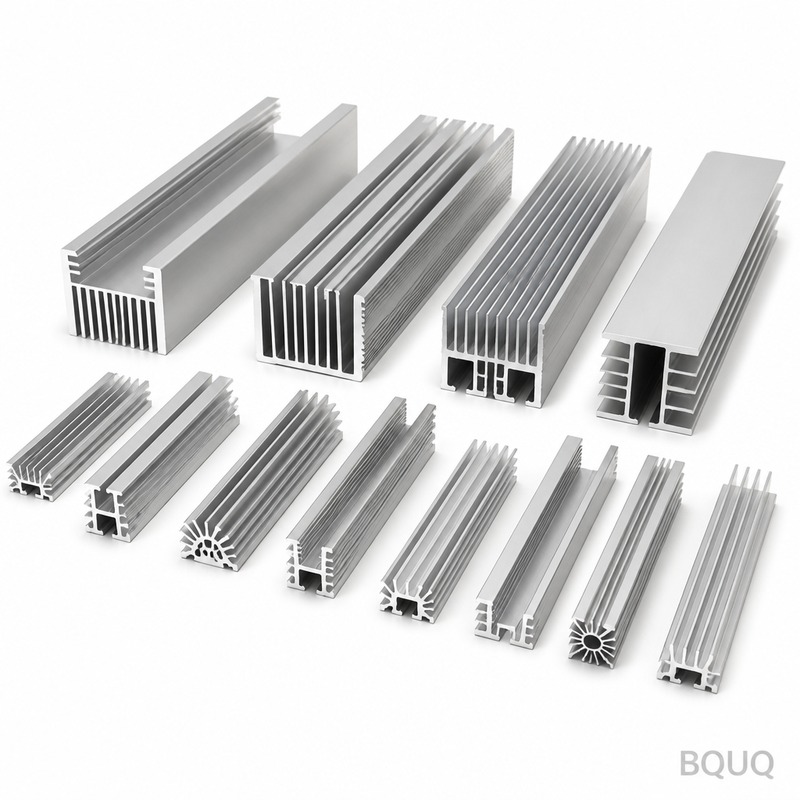
For most industrial and commercial LED applications, 6063-T5 aluminum extruded heat sinks are the industry standard. The thermal conductivity of 201 W/m·K is sufficient for heat fluxes below 10W/cm². Copper is reserved for applications where space is constrained and heat flux exceeds 20W/cm², such as in automotive headlamps or high-lumen projector modules. At BQUQ, we recommend CNC-machined 6061-T6 for prototypes and low-volume production (under 500 units) because it offers better dimensional tolerance (±0.05mm) compared to extrusion (±0.2mm).
Critical Design Parameters: Fin Geometry and Surface Area
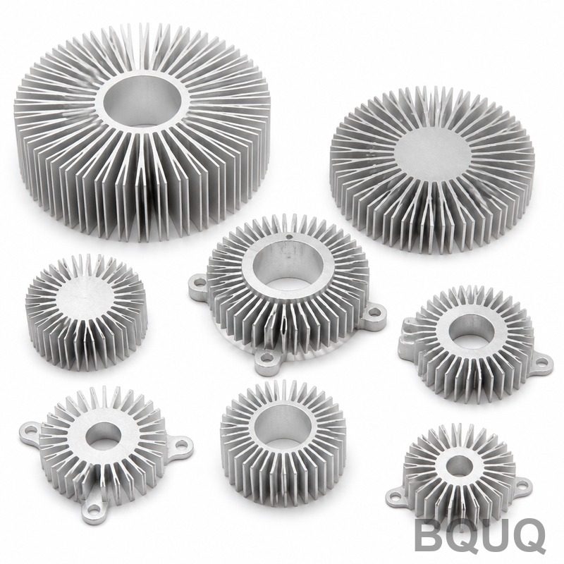
Heat sink performance is governed by Newton's Law of Cooling, which states that heat dissipation is proportional to surface area and the temperature difference between the sink and ambient air. The design must optimize fin thickness, fin spacing, and base plate thickness. For natural convection (no fan), the optimal fin spacing is 6-8mm, with fin thickness of 2-3mm and fin height of 20-40mm. This geometry allows air to flow freely via buoyancy while maximizing surface area.
For a 50W LED system requiring a Tj of 85°C at 40°C ambient, the heat sink must dissipate 35W of heat (assuming 70% conversion to heat). With a maximum allowable case temperature of 75°C, the thermal resistance required is (75-40)/35 = 1.0°C/W. A natural convection heat sink with dimensions 200mm x 120mm x 40mm (fin height) with 15 fins of 2.5mm thickness will provide approximately 1.05°C/W. For forced convection (0.5m/s airflow), the same heat sink provides 0.6°C/W, allowing a 30% reduction in size.
The base plate thickness is equally critical. A thin base plate (under 5mm) creates thermal spreading resistance, causing hotspots directly under the LED. For a 10mm x 10mm COB LED, the base plate should be at least 8mm thick to ensure uniform temperature distribution across the heat sink. CNC machining allows precise control of base plate thickness, with tolerances of ±0.1mm, ensuring consistent thermal performance across production batches.
Surface Treatment: Anodizing and Black Coating
Surface treatment plays a significant role in heat dissipation, particularly for radiation. While conduction and convection account for the majority of heat transfer (85-90%), radiation accounts for 10-15% at typical operating temperatures of 60-80°C. A black anodized surface has an emissivity of 0.88-0.95, compared to 0.15-0.25 for polished aluminum. This difference can reduce the required heat sink surface area by 10-15%.
At BQUQ, we use a sulfuric acid anodizing process to create a 15-25 micron thick oxide layer. This layer not only improves emissivity but also provides corrosion resistance and electrical insulation. The anodizing process costs approximately $0.50-$1.00 per square meter of surface area, which is a minimal cost compared to the 10-15% reduction in aluminum material required. For outdoor LED fixtures exposed to salt air or high humidity, we recommend a sealed anodized finish to prevent oxidation, which can degrade thermal performance over time.
CNC Machining Tolerances and Cost Implications
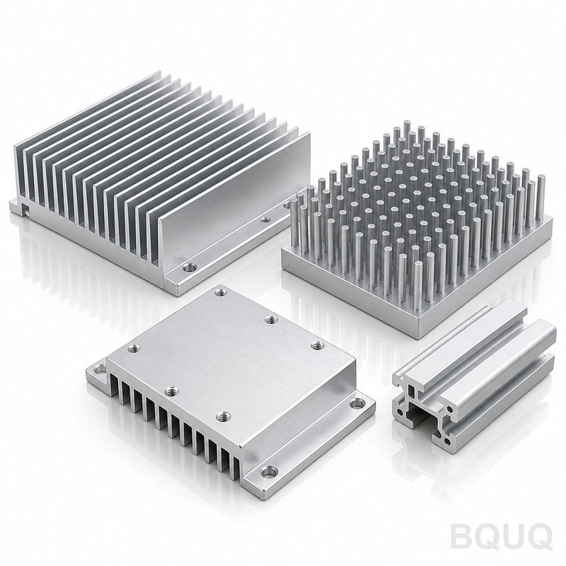
When designing a custom LED heat sink, the manufacturing process dictates the achievable tolerances and cost. CNC machining offers the highest precision and flexibility but comes at a premium. The table below shows typical specifications for CNC-machined heat sinks at BQUQ.
| Parameter | CNC Machining Tolerance | Stamping Tolerance | Extrusion Tolerance |
| Fin Thickness | ±0.05mm | ±0.10mm | ±0.30mm |
| Fin Spacing | ±0.10mm | ±0.20mm | ±0.50mm |
| Base Plate Thickness | ±0.10mm | ±0.15mm | ±0.30mm |
| Surface Roughness (Ra) | 1.6-3.2μm | 3.2-6.3μm | 3.2-6.3μm |
| Minimum Fin Thickness | 0.8mm | 1.5mm | 1.8mm |
| Lead Time (100 pcs) | 3-5 days | 7-10 days | 10-14 days |
| Tooling Cost | $0 | $500-$2,000 | $2,000-$5,000 |
For a typical 40W LED heat sink measuring 150mm x 100mm x 30mm, CNC machining costs range from $8-$15 per unit at quantities of 100-500 pieces. At 5,000+ pieces, stamping becomes more economical at $3-$6 per unit, but requires a minimum fin thickness of 1.5mm and introduces residual stress that can cause warpage if not properly stress-relieved. For high-volume production over 10,000 units, extrusion is the most cost-effective at $2-$4 per unit, but the design must maintain uniform wall thickness and avoid sharp corners.
Practical Recommendations for Engineers
1. Always calculate the required thermal resistance (Rθsa) before selecting a heat sink. Use the formula Rθsa = (Tj_max - T_ambient - P_total x Rθjc - P_total x Rθcs) / P_heat. For a 50W LED with Rθjc of 0.5°C/W and Rθcs of 0.1°C/W, at 25°C ambient and 85°C max Tj, the required Rθsa is (85-25-50x0.5-50x0.1)/35 = 0.86°C/W.
2. Position the LED at the center of the base plate to maximize thermal spreading. Offset mounting increases the thermal path length by 30-50% and creates temperature gradients of 5-10°C across the sink.
3. Use thermal interface material (TIM) with a minimum thermal conductivity of 3W/m·K. A 0.1mm thick TIM with 5W/m·K conductivity has a thermal resistance of 0.02°C·cm²/W, compared to 0.1°C·cm²/W for a dry joint. The cost difference is $0.10 per application, which is negligible versus a 5°C reduction in Tj.
4. For outdoor applications, derate the heat sink by 20% in surface area to account for dust accumulation and reduced convection in windless conditions. A 50W indoor design requires 0.02m² of surface area, but an outdoor version requires 0.025m².
5. Always prototype with CNC machining before committing to stamping or extrusion tooling. A CNC prototype costs $50-$150 and takes 2-3 days, allowing you to validate thermal performance with a thermocouple test before investing $2,000-$5,000 in tooling.
FAQ-Style Design Tips
Question: How do I know if my heat sink is undersized? Answer: Measure the case temperature with a thermocouple at the LED mounting point. If the case temperature exceeds 75°C at 25°C ambient, the heat sink is undersized. The junction temperature is approximately 5-10°C higher than the case temperature for typical LED packages.
Question: Can I use a fan instead of a larger heat sink? Answer: Yes, but forced convection has reliability implications. A 40mm fan has a mean time between failures (MTBF) of 30,000-50,000 hours, which is shorter than the LED lifespan. If using a fan, design for 50% redundancy or use a larger heat sink with a fan only as a backup for extreme ambient conditions.
Question: What is the maximum ambient temperature for LED fixtures? Answer: For standard LEDs rated at 85°C junction temperature, the maximum ambient temperature is typically 50-60°C with a properly sized heat sink. Above 60°C ambient, you must either derate the LED current or use a liquid cooling system, which is rare in commercial applications.
Conclusion and Manufacturing Considerations
Thermal management is not an afterthought in LED design; it is the primary determinant of product lifespan, luminous flux maintenance, and color stability. By maintaining junction temperature below 85°C, you ensure 70% lumen maintenance at 50,000 hours, which is the industry benchmark for quality LED fixtures. Neglecting thermal design reduces lifespan to 15,000-20,000 hours, equivalent to a 60-70% reduction in usable life.
The manufacturing process you choose affects both thermal performance and cost. CNC machining offers the tightest tolerances and design flexibility, making it ideal for prototypes and medium-volume production. At BQUQ, our 20 years of experience in CNC machining, metal stamping, and heat sink fabrication ensures we can produce custom thermal solutions with tolerances of ±0.05mm and lead times of 3-5 days for prototypes.
For your next LED project, send us your thermal requirements and mechanical constraints. Our engineering team will provide a thermal simulation and a detailed quote within 12 hours, including material selection, surface treatment options, and cost breakdown for your target volume. Contact us at sc@bquq.com or WhatsApp +86 13713157787. Visit www.bquq.com to download our heat sink design guide and standard product catalog.
Related Articles
- Best Copper Heat Sinks for CPU Overclocking in 2025
- Stamped Metal vs Die Cast Heat Sinks: Cost & Quality Comparison
- 5G Base Station Outdoor AAU Cooling: The Climate Adaptation Challenge of Fanless Passive Design
Frequently Asked Questions
What is the typical lifespan of an LED with a properly designed heat sink?
With proper heat sink design keeping junction temperature below 85°C for standard LEDs or below 105°C for high-power variants, the rated lifespan is 50,000 to 100,000 hours. Without adequate thermal management, premature failure can occur at around 10,000 hours.
Why is a heat sink necessary for high-power LEDs?
A typical high-power LED converts only 30-40% of input electrical power into visible light; the remaining 60-70% becomes heat. For a 10W LED, this means 6-7W of heat must be conducted away. Without a heat sink, junction temperature exceeds 150°C within seconds, causing spectral shift, lumen depreciation, and catastrophic failure.
Which heat sink material is recommended for most industrial LED applications?
6063-T5 aluminum extruded heat sinks are the industry standard for most industrial and commercial LED applications, with thermal conductivity of 201 W/m·K, sufficient for heat fluxes below 10W/cm². Copper is reserved for space-constrained applications with heat flux exceeding 20W/cm², such as automotive headlamps.
What are the dimensional tolerances for CNC-machined versus extruded heat sinks?
CNC-machined 6061-T6 aluminum offers better dimensional tolerance at ±0.05mm, compared to extrusion which provides ±0.2mm. This makes CNC machining the recommended choice for prototypes and low-volume production under 500 units, where precision is critical.


