
Liquid Cold Plate vs Air Cooled Heat Sink: Which Cooling Solution?
For most applications below 150 W/cm² heat flux, an air cooled heat sink is the more cost-effective and reliable choice, while a liquid cold plate becomes mandatory when heat density exceeds 200 W/cm² or when ambient temperatures are above 50°C. Liquid cold plates offer 10-50 times better thermal conductivity than air cooling but require pumps, tubing, and leak management, increasing system cost by 300-500%. The correct selection depends on your specific heat load, available space, and environmental constraints, not on a universal "best" option.
What Are the Fundamental Thermal Performance Differences Between Liquid Cold Plates and Air Cooled Heat Sinks?
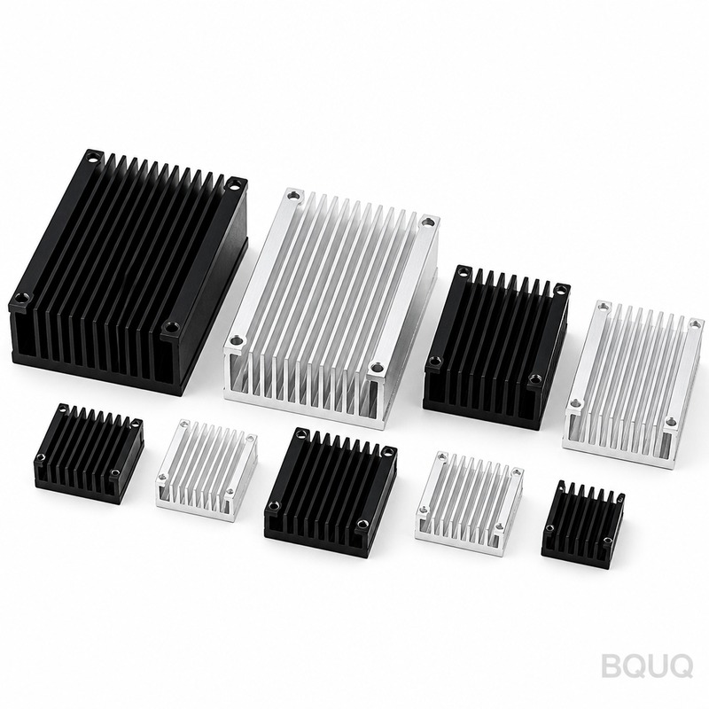
Air cooled heat sinks rely on natural or forced convection, with typical thermal resistance values ranging from 0.1°C/W to 1.0°C/W depending on fin density and airflow. A standard extruded aluminum heat sink with a 5 m/s airflow can dissipate 50-150 W from a 40 mm x 40 mm IGBT package, maintaining a junction-to-ambient temperature rise of 40-60°C. In contrast, a liquid cold plate with a 1.5 mm microchannel structure and 6 L/min water flow achieves thermal resistance of 0.02-0.08°C/W, enabling heat dissipation of 500-2000 W from the same footprint while keeping the case temperature below 65°C. The liquid solution excels in high-density scenarios because water has a specific heat capacity of 4.18 kJ/(kg·K), roughly 3,500 times greater than air at 1.005 kJ/(kg·K) per unit volume.
How Do System Costs and Total Cost of Ownership Compare?
A typical air cooled heat sink for a 100 W power electronics module costs $8-$25 for the extruded aluminum part, plus $3-$10 for a DC fan, yielding a total of $11-$35 per unit. A liquid cold plate system requires the cold plate itself ($40-$150 for a copper or aluminum microchannel unit), a pump ($15-$60), a radiator ($20-$80), tubing and fittings ($10-$30), and coolant ($5-$15), totaling $90-$335 per unit. Over a 10-year lifespan, air cooling incurs higher energy costs due to fan power consumption of 5-15 W versus pump power of 2-8 W, but maintenance costs for liquid systems are 2-3 times higher due to pump replacement every 3-5 years and potential corrosion issues. For production volumes above 1,000 units, liquid cold plate tooling costs of $5,000-$15,000 amortize to $5-$15 per part, reducing the gap but not eliminating the 3-5x cost premium.
Which Applications Require a Liquid Cold Plate Instead of an Air Cooled Heat Sink?
You must switch to a liquid cold plate when the heat flux exceeds 150-200 W/cm², which occurs in laser diodes, high-power IGBT modules for EV inverters, and server CPUs with TDP above 350 W. For example, a 300 W GPU in a 2U server with 40 mm height cannot fit a sufficient air cooled fin stack because the required fin surface area would need a minimum of 1,200 cm², which is physically impossible in that envelope. Liquid cold plates are also mandatory in sealed enclosures (IP65 or higher) where air exchange is prohibited, such as in offshore wind turbine converters or electric vehicle battery packs operating at 40°C ambient, where air cooling would require oversized ducts and fans. If your application has heat density below 100 W/cm² and you have at least 25 mm of clearance for fins, an air cooled heat sink with a properly sized fan will always be more reliable and cost-effective.
How Do Size, Weight, and Packaging Constraints Affect the Choice?
Air cooled heat sinks typically require 3-5 times more volume than liquid cold plates for the same thermal performance. A 500 W liquid cold plate measures 150 mm x 100 mm x 15 mm (0.23 L volume, 0.8 kg), while an equivalent air cooled heat sink with forced convection needs 200 mm x 150 mm x 80 mm (2.4 L volume, 1.8 kg with fan). In weight-sensitive applications like aerospace or portable medical devices, the liquid system with a remote radiator can save 40-60% of total weight by placing the heavy mass away from the heat source. However, liquid cold plates require a minimum bend radius of 25 mm for tubing and a pump head of 1-2 bar, which adds design complexity and may not fit in ultra-compact consumer electronics below 10 mm thickness.
What Are the Reliability and Maintenance Trade-Offs in Real Factory Conditions?
Air cooled heat sinks have a mean time between failures (MTBF) of 50,000-100,000 hours for the fan, but the heat sink itself is essentially maintenance-free for 20+ years. Liquid cold plates have a pump MTBF of 20,000-50,000 hours, and the system requires coolant replacement every 2-3 years to prevent biological growth and particle accumulation. In dusty factory environments (common in CNC machining facilities), air cooled fins clog within 6-12 months, reducing performance by 20-40% unless filters are used; liquid systems are immune to dust but suffer from galvanic corrosion if aluminum and copper are mixed without proper inhibitors. Our 20 years of manufacturing data at BQUQ shows that liquid cold plate leaks occur at a rate of 0.5-2% per year, primarily at fitting connections, whereas air cooled systems have a zero-leak failure mode.
Why Does Thermal Interface Material (TIM) Selection Matter More for Liquid Cold Plates?
Liquid cold plates require a TIM with thermal conductivity above 5 W/(m·K) because the cold plate surface temperature is only 10-20°C above the coolant temperature, leaving less margin for interface resistance. A typical 0.1 mm thick thermal pad with 3 W/(m·K) conductivity adds 0.033°C·cm²/W of resistance, which is acceptable for air cooling but represents 15-30% of the total thermal budget in a liquid system. For liquid cold plates, we recommend using phase-change materials or solder-based TIMs (conductivity of 20-50 W/(m·K)) to keep the junction-to-case resistance below 0.05°C/W. Air cooled systems can tolerate lower-grade TIMs, but we still recommend a minimum of 3 W/(m·K) to avoid hot spots at the die corners.
Which Manufacturing Processes Produce the Best Liquid Cold Plates and Heat Sinks?
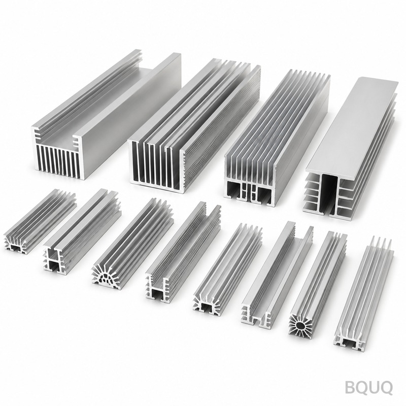
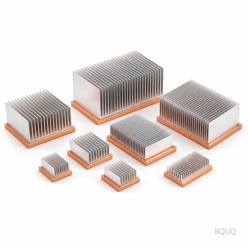
At BQUQ, we manufacture liquid cold plates using CNC machining of copper (C1020, thermal conductivity 391 W/(m·K)) or aluminum (6063-T5, 201 W/(m·K)), achieving channel tolerances of ±0.05 mm and surface flatness of 0.02 mm over 200 mm length. For high-volume production, we use vacuum brazing to join the cover plate to the finned base, which produces a leak-tight joint rated at 10 bar with a helium leak rate below 1 x 10^-8 mbar·L/s. Air cooled heat sinks are produced by aluminum extrusion (6000-series alloys) with fin thickness of 1.0-2.5 mm and fin pitch of 4-10 mm, followed by CNC milling for critical mounting surfaces and anodizing to 10-25 µm thickness for corrosion resistance. For heat sinks above 300 W, we recommend skived fin technology, which produces fins as thin as 0.3 mm with a height-to-thickness ratio of 40:1, offering 20% better performance than extruded equivalents.
What Are the Key Performance Metrics for Comparison?
| Parameter | Air Cooled Heat Sink | Liquid Cold Plate |
| Thermal resistance | 0.1-1.0°C/W | 0.02-0.08°C/W |
| Maximum heat flux | 50-150 W/cm² | 200-1000 W/cm² |
| System cost (100 W module) | $11-$35 | $90-$335 |
| Volume for 500 W | 2.4 L | 0.23 L |
| Weight for 500 W | 1.8 kg | 0.8 kg |
| MTBF | 50,000-100,000 hrs (fan) | 20,000-50,000 hrs (pump) |
| Maintenance interval | None (dust cleaning) | Coolant change every 2-3 years |
| Leak risk | None | 0.5-2% per year |
| Ambient temperature limit | Up to 50°C | Up to 70°C with coolant at 40°C |
Which Cooling Solution Should You Choose for Your Specific Product?
For consumer electronics, LED lighting, and industrial power supplies below 200 W, always choose an air cooled heat sink because it offers the lowest cost, zero maintenance, and adequate performance. For EV chargers, laser systems, and high-performance computing above 300 W or with heat flux above 150 W/cm², choose a liquid cold plate despite the higher complexity, because air cooling would require an impractically large fin array. In hybrid scenarios where you have moderate heat (150-300 W) but tight space constraints, consider a vapor chamber or heat pipe-based air cooled solution as a compromise, offering 2-3x better performance than solid aluminum at 1.5-2x the cost.
What Is the Best Way to Prototype and Validate Your Cooling Solution?
We recommend starting with a thermal simulation using computational fluid dynamics (CFD) to estimate junction temperature with a target of 85°C for silicon and 125°C for silicon carbide devices. For air cooled solutions, order extruded heat sink samples with 3-5 different fin densities (e.g., 4 mm, 6 mm, 8 mm pitch) and test with a 50 W or 100 W heater block using thermocouples at the base and fins. For liquid cold plates, request a CNC-machined prototype with your exact channel geometry, test at flow rates of 2, 4, and 6 L/min, and verify pressure drop below 1 bar to ensure your pump can handle it. Always measure thermal resistance using the ASTM D5470 standard or the transient dual interface method, and confirm that your TIM application method (paste dispensing, pad, or solder preform) is repeatable in production.
What Are the Common Mistakes Engineers Make When Selecting Between These Two Technologies?
The most frequent error is sizing the air cooled heat sink based on average power rather than peak power, which leads to overheating during transient loads; always design for the worst-case 10-second burst. Another mistake is ignoring the fan curve and assuming that a larger fan always moves more air, when in reality the static pressure must overcome the fin resistance, so a blower fan is needed for high-density fins. For liquid systems, engineers often undersize the radiator, forgetting that the radiator must reject the total heat load to ambient; a rule of thumb is 1 kW of heat requires 0.3-0.5 m² of radiator surface area with a 20°C temperature difference. Finally, never mix aluminum and copper in the same liquid loop without a corrosion inhibitor, as galvanic corrosion will perforate the components within 6-12 months.
What Is the Future Trend Toward Hybrid Cooling Solutions?
We are seeing a shift toward hybrid liquid-air systems in data centers, where a liquid cold plate handles the CPU (80% of heat) and a small air cooled heat sink manages the VRM and memory (20% of heat), reducing total liquid volume by 40%. Another emerging technology is two-phase immersion cooling, which uses dielectric fluids boiling at 60°C to achieve heat transfer coefficients of 5,000-10,000 W/(m²·K), but this is currently 3-5x more expensive than liquid cold plates. For automotive applications, we recommend a dual-loop system: a liquid cold plate for the inverter and a conventional air cooled heat sink for the DC-DC converter, optimizing cost and performance for each thermal zone.
Which Cooling Solution Offers Better Long-Term Value for a 10-Year Product Lifespan?
Air cooled heat sinks deliver lower total cost of ownership for products under 200 W, with a 10-year cost of $50-$100 including fans and energy, versus $400-$800 for a liquid system with pump replacements and maintenance. For high-power products above 500 W, liquid cold plates are the only viable option, and the 10-year cost of $1,500-$2,500 is justified by the system's ability to operate at 95% efficiency without derating. The break-even point where liquid becomes more cost-effective than air is approximately 300 W continuous heat dissipation with a 40°C ambient temperature, assuming a 10-year operating period at 8,760 hours per year.
Frequently Asked Questions
Can I Convert an Existing Air Cooled Design to a Liquid Cold Plate Without Redesigning the PCB?
Yes, but you must remount the heat-generating components to a flat cold plate surface with a planarity of 0.05 mm or better, and you need to add mounting holes with a torque specification of 0.5-0.8 N·m to ensure even TIM compression. The PCB layout can remain the same, but you must reserve a 25 mm clearance around the cold plate for inlet and outlet fittings.
What Coolant Flow Rate Do I Need for a 500 W Heat Load?
For a 500 W load with a 10°C temperature rise across the cold plate, you need a flow rate of at least 0.72 L/min, calculated as 500 W divided by (4.18 kJ/(kg·K) times 10°C times 1 kg/L). We recommend a design flow of 2-4 L/min to account for parallel channels and manufacturing tolerances, giving a pressure drop of 0.3-0.8 bar.
How Often Should I Replace the Coolant in a Liquid Cold Plate System?
Replace the coolant every 2 years for industrial environments and every 3 years for clean room applications, or when the electrical conductivity exceeds 500 µS/cm. Use a propylene glycol-water mixture at 30-50% concentration with a corrosion inhibitor package rated for both copper and aluminum.
What Is the Maximum Fin Height I Can Achieve in an Extruded Heat Sink?
Standard aluminum extrusion can achieve fin heights up to 75 mm with a fin thickness of 1.5 mm and a height-to-width ratio of 20:1, while skived fin technology reaches 150 mm height with 0.3 mm fins. For heights above 150 mm, you must switch to a bonded fin or folded fin design, which adds 20-30% to the manufacturing cost.
Does Anodizing Improve the Thermal Performance of an Air Cooled Heat Sink?
Anodizing improves emissivity from 0.05 (bare aluminum) to 0.85, which enhances radiative heat transfer by 10-15% in natural convection but has negligible effect in forced convection. The anodized layer adds 10-25 µm of thickness with a thermal conductivity of 1-2 W/(m·K), which is acceptable if the coating remains below 50 µm.
What Is the Maximum Coolant Temperature I Can Use Without Damaging the Electronics?
The coolant temperature at the cold plate inlet should not exceed 60°C for silicon devices with a junction limit of 125°C and 70°C for silicon carbide devices, assuming a 10°C temperature rise across the cold plate. For the radiator, the coolant outlet temperature should be kept at least 10°C below the ambient boiling point to prevent cavitation in the pump.
How Do I Test the Leak Integrity of a Liquid Cold Plate in Production?
Use a helium mass spectrometer leak test with a detection limit of 1 x 10^-8 mbar·L/s, which is 100 times more sensitive than a water pressure test. Alternatively, perform a pneumatic test at 10 bar for 30 minutes and check for pressure drop below 0.1 bar, followed by a dye penetration test on the braze joints.
We provide free thermal design reviews and 3D CAD recommendations within 12 hours of receiving your specifications. For a quick quotation or technical consultation, contact our engineering team at sc@bquq.com, reach us on WhatsApp at +86 13713157787, or visit www.bquq.com to upload your thermal requirements and receive a same-day response.


