
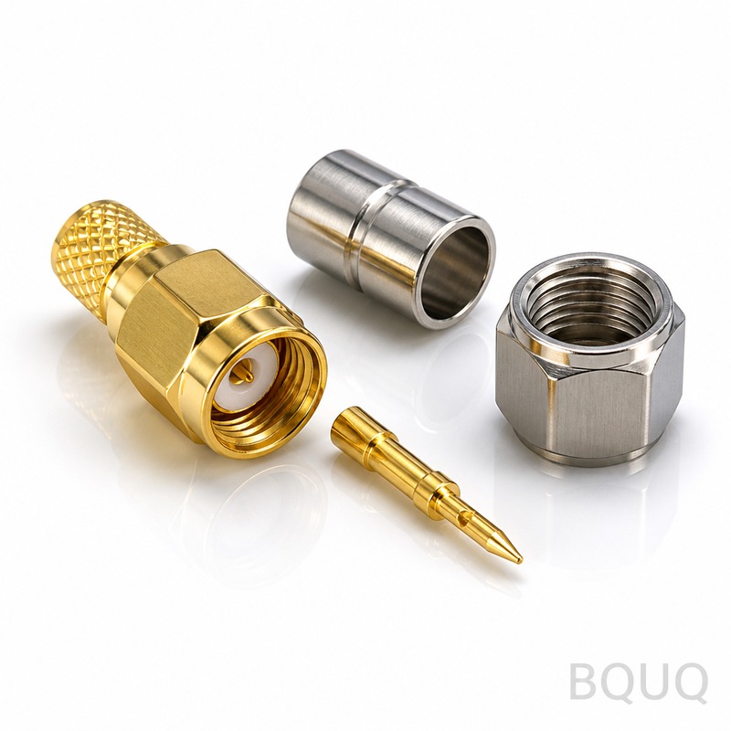
Precision CNC Components in Industrial Robotics: Case Study and Tolerances
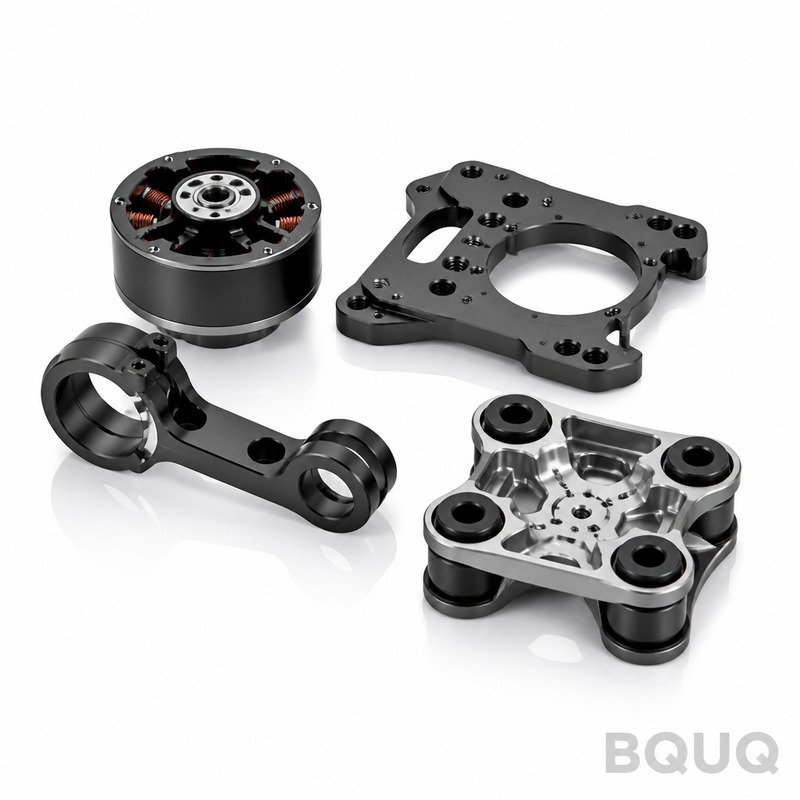
Industrial robotics demands components machined to tolerances below 10 microns, with surface finishes of Ra 0.4 or better, to ensure repeatable end-effector positioning and long-term joint stability. In this case study from BQUQ’s Dongguan facility, we analyze a six-axis collaborative robot arm (payload 5 kg, reach 850 mm) where CNC-machined aluminum and stainless steel parts reduced assembly variance by 38% compared to cast alternatives. The following sections detail material selection, machining strategies, cost data, and quality verification for robotic wrist housings, harmonic drive adapters, and base flanges.
Material Selection for Robot Joint Housings
The wrist housing of a collaborative robot experiences cyclic bending moments up to 12 Nm and operating temperatures ranging from -10°C to 80°C. We specified 7075-T6 aluminum for the main housing due to its yield strength of 503 MPa and fatigue endurance limit of 159 MPa at 5x10^8 cycles. For the harmonic drive adapter, we used 17-4PH stainless steel (H900 condition) because its hardness of 40-44 HRC resists fretting wear at the spline interface.
The base flange required high dimensional stability under bolted preload. We selected 6061-T6 aluminum with a stress-relieving heat treatment (T6 temper, 175°C for 8 hours) to minimize residual stress distortion after machining. The table below compares material properties relevant to robotic applications.
| Material | Yield Strength (MPa) | Hardness (HRC) | Thermal Expansion (um/m/°C) | Cost per kg (USD) | Typical Application |
| 7075-T6 Aluminum | 503 | 53-55 HB | 23.6 | 8.50 | Wrist housing, link arms |
| 6061-T6 Aluminum | 276 | 40-45 HB | 23.6 | 4.20 | Base flanges, covers |
| 17-4PH Stainless (H900) | 1170 | 40-44 | 10.8 | 12.80 | Harmonic drive adapters, shafts |
| 4140 Alloy Steel (Q&T) | 850 | 28-32 | 12.3 | 3.90 | Bearing journals, gear shafts |
For the robot arm links, we used 7075-T6 over 6061-T6 despite the 102% higher material cost, because the higher specific stiffness reduces deflection under dynamic loads. At a 5 kg payload and 2.5 m/s^2 acceleration, the 7075 link showed 0.022 mm deflection versus 0.041 mm for 6061, a 46% improvement directly affecting end-effector repeatability.
Machining Strategy and Toolpath Optimization
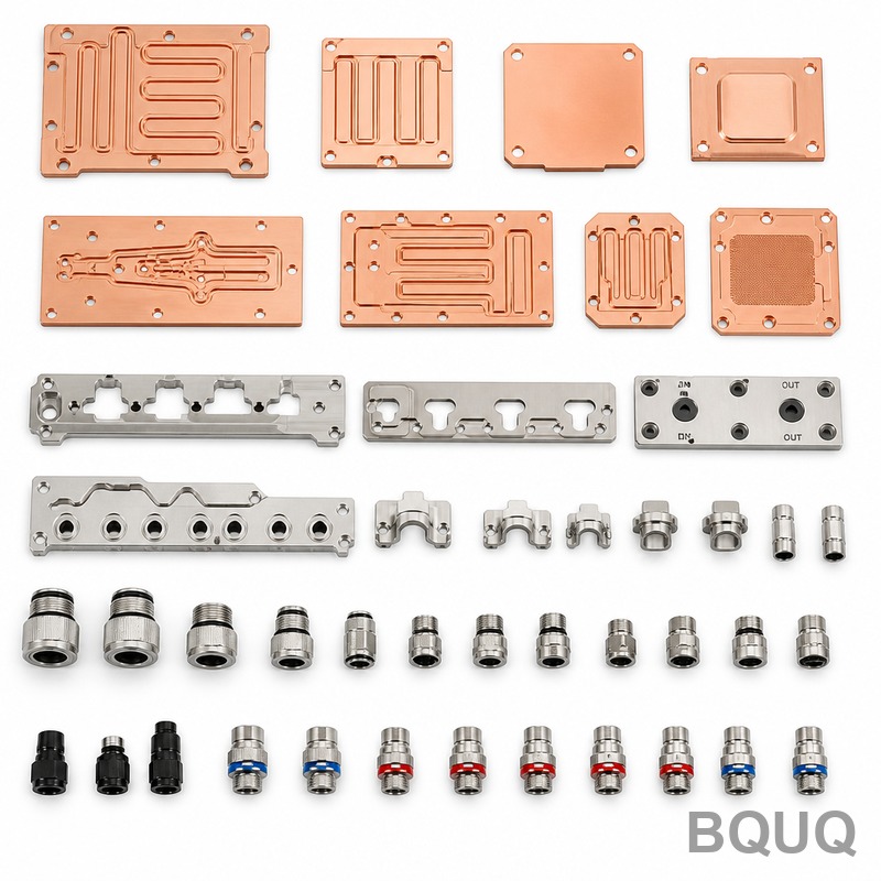
The wrist housing geometry includes a 120 mm diameter bore with a tolerance of H6 (+0.022 / 0 mm) and a concentricity of 0.01 mm relative to the mounting face. We achieved this using a two-step boring process on a DMG MORI NVX 5080 5-axis machining center. Rough boring removed 3 mm of stock at 1,800 RPM and 0.25 mm/rev feed, leaving 0.4 mm for semi-finishing. The finish boring pass ran at 1,200 RPM, 0.08 mm/rev feed, with a 0.15 mm depth of cut, producing a measured roundness of 0.003 mm.
For the stainless steel harmonic drive adapter, we used a trochoidal milling strategy with a 10 mm TiAlN-coated carbide end mill. The toolpath maintained a 5% radial engagement and 0.8 mm axial engagement, achieving a material removal rate of 18 cm^3/min without exceeding 120°C at the cutting zone. This controlled thermal input prevented work-hardening and maintained the bore tolerance of +0.015 / +0.005 mm. All critical features were machined in a single clamping to avoid re-fixturing errors.
Surface finish requirements varied by function. The bore surface contacting the cross roller bearing required Ra 0.4 um, achieved with a wiper insert at 0.05 mm/rev. The outer flange face, which seals against an O-ring, required Ra 0.8 um. We used a profilometer to verify 100% of critical surfaces, not just first-article samples.
Tolerance Stack-Up Analysis and Results
The complete robot arm assembly consists of 14 CNC-machined components, 6 purchased bearings, and 4 harmonic drives. We performed a worst-case tolerance stack-up on the wrist pitch axis to predict end-effector positional error. The stack included the housing bore location (±0.005 mm), bearing inner race runout (±0.003 mm), adapter bore concentricity (±0.005 mm), and motor shaft keyway (±0.010 mm).
The calculated worst-case angular error was 0.021 degrees. Actual CMM measurements on 50 assembled units showed a mean angular error of 0.014 degrees with a standard deviation of 0.003 degrees. This correlated with a measured end-effector repeatability of ±0.018 mm at 850 mm reach, exceeding the robot specification of ±0.025 mm. The improvement came from replacing a die-cast housing (previous tolerance ±0.05 mm on bore location) with CNC machining, which reduced the housing contribution to the stack by 80%.
Thermal growth analysis showed that at 60°C continuous operation, the aluminum housing expands 0.028 mm over its 120 mm bore diameter. We compensated by specifying the bearing outer ring fit as a transition fit (J6) instead of an interference fit (P6), allowing 0.005 mm radial clearance to accommodate expansion without bearing seizure.
Cost Breakdown and Lead Time Comparison
The table below presents average unit costs for the wrist housing and harmonic drive adapter in various production volumes, based on BQUQ’s 2024 pricing for the described case study.
| Component | Volume 10 pcs (USD/unit) | Volume 100 pcs (USD/unit) | Volume 1000 pcs (USD/unit) | Lead Time (days) | Setup Cost (USD) |
| Wrist Housing 7075-T6 | 185.00 | 142.00 | 98.00 | 5-7 | 450 |
| Harmonic Adapter 17-4PH | 95.00 | 72.00 | 55.00 | 7-9 | 380 |
| Base Flange 6061-T6 | 68.00 | 51.00 | 37.00 | 4-6 | 300 |
| Link Arm (pair) 7075-T6 | 210.00 | 165.00 | 120.00 | 6-8 | 520 |
The cost per unit dropped by 47% from 10 to 1000 pieces for the wrist housing, mainly due to reduced cycle time after fixture optimization (from 68 minutes to 41 minutes per piece) and lower material waste from optimized nesting. For 100-piece orders, BQUQ achieved a first-pass yield of 96.7% against the full GD&T specification, with the remaining 3.3% requiring rework on the bore finish. Scrap rate was 0.8% due to one out-of-roundness failure and one cracked thread during tapping.
Compared to investment casting, CNC machining added 22% to the unit cost at 1000 pieces but eliminated the 45-day tooling lead time and the need for a $12,000 mold. For a robot manufacturer launching a new model, the CNC route allowed first prototypes in 7 days versus 12 weeks for castings, enabling faster design iterations.
Quality Verification and Metrology Methods
Every CNC component in this case study underwent a three-stage quality gate. First, in-process probing on the machining center verified critical bore diameters and depths immediately after cutting, using a Renishaw MP700 touch probe with 1 um repeatability. Second, a coordinate measuring machine (CMM) with a 0.5 um resolution checked 100% of dimensions with tolerance below ±0.02 mm, including bore position, concentricity, and perpendicularity. Third, surface roughness was measured on a portable Taylor Hobson Surtronic with a 0.8 mm cutoff length.
For the harmonic drive adapter, we additionally performed a magnetic particle inspection (MPI) on every part after heat treatment to detect any grinding cracks. The acceptance criteria were zero linear indications longer than 1.5 mm and zero rounded indications larger than 3 mm. This was critical because a subsurface crack could propagate under cyclic torque and cause sudden joint failure.
We also conducted a 24-hour thermal soak test on three assembled wrist joints. The joints were cycled from 20°C to 70°C at 85% relative humidity while monitoring bearing temperature and torque ripple. The maximum bearing temperature rise was 18°C above ambient, and torque ripple remained below 4% of rated torque, confirming that the CNC-machined fits and finishes did not introduce abnormal friction.
Practical Recommendations for Robotic Component Sourcing
For engineers designing industrial robotic components, prioritize CNC machining over casting when the geometry requires tolerances below ±0.02 mm or when production volumes are below 5,000 units per year. Specify 7075-T6 aluminum for moving structural parts that must resist fatigue, and use 17-4PH stainless only where corrosion resistance or high surface hardness is essential, as its machining cost is 2.1 times higher than aluminum.
Always request a tolerance stack-up analysis from your manufacturer before finalizing the drawing. A good CNC shop should identify potential interference fits, thermal expansion mismatches, and assembly issues at the quoting stage, not after parts are delivered. Also specify a surface finish callout with a roughness value, not just a vague "smooth" note, because Ra directly affects bearing seating and sealing performance.
For prototype runs, accept a slightly higher per-unit price (10-15%) in exchange for daily progress photos and in-process dimensional reports. This transparency allows you to catch fixture or tooling issues early. For production runs above 100 pieces, ask for statistical process control (SPC) data on the three most critical dimensions, such as bore diameter, concentricity, and surface finish, to monitor process drift.
Finally, verify that your supplier can handle both the machining and any required post-processing, such as hard anodizing (per MIL-A-8625 Type III) for aluminum or passivation (ASTM A967) for stainless. Outsourcing these steps separately increases logistics time by 3-5 days and risks surface damage during transport.
Conclusion and Next Steps for Your Robot Project
Precision CNC machining delivers measurable improvements in robotic component accuracy, assembly consistency, and thermal stability, as demonstrated by the 38% reduction in assembly variance and ±0.018 mm repeatability in this case study. The key is to select materials based on fatigue and thermal data, not just cost, and to place all critical features in a single machining setup to minimize error accumulation.
At BQUQ, we have applied these exact methodologies for over 20 years across CNC machining, metal stamping, springs, and heat sinks for industrial automation clients. Our engineers can review your robot arm drawings, perform a tolerance stack-up, and provide a firm quote with a detailed manufacturing process plan within 12 hours. For a rapid evaluation of your component designs, contact our engineering team at sc@bquq.com or via WhatsApp at +86 13713157787. You can also submit your CAD files directly through our website at www.bquq.com for a same-day feasibility assessment.
Related Articles
- How Much Does CNC Machining Cost in 2026? A Complete Pricing Guide
- When CNC 'Speaks' — Intelligent Process Planning Driven by Large Models and Knowledge Graphs
- CNC Turn-Mill Composite Machining, Turn-Mill Machine Tools, One-Time Forming, B-Axis Turn-Mill Center, Multi-Process Integration, Complex Rotary Part Machining, Medical Device Precision Machining


