Progressive Die Stamping Explained: Process, Tolerances, and Cost Efficiency
Progressive Die Stamping Explained: Process, Tolerances, and Cost Efficiency
**Direct Answer:** Progressive die stamping is a high-speed metal forming process where a continuous coil strip is fed through a multi-station die, with each station performing a distinct cutting, bending, or drawing operation until a finished part is ejected. It is the most cost-effective method for producing high volumes (typically 50,000+ parts) of complex sheet metal components with tolerances as tight as ±0.01 mm. The process works by synchronizing a press stroke with a precision-indexed feed mechanism, ensuring each station completes its operation on every stroke, yielding one finished part per press cycle.
1. The Core Mechanics: How the Die and Press Interact
Progressive die stamping operates on a simple principle: a strip of metal (usually 0.1 mm to 6.0 mm thick) is advanced incrementally through a die set mounted in a press. Each station in the die performs a specific operation—piercing, notching, trimming, forming, coining, or drawing—in a sequential order.
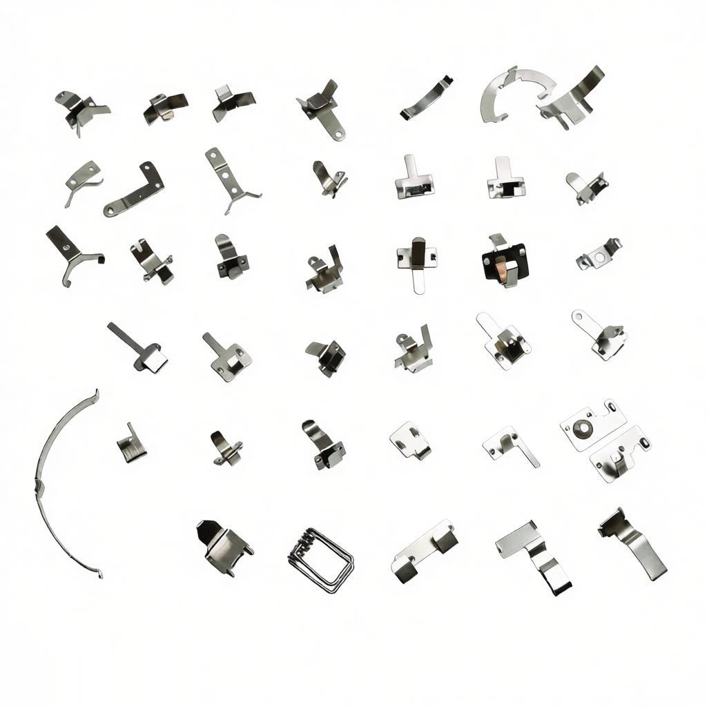
The press, typically a mechanical or servo-driven machine, provides the vertical force. Stroke rates range from 30 to 1,200 strokes per minute (SPM) depending on part size and material. The die is mounted with a stripper plate that holds the strip down while the punch retracts, preventing the metal from lifting. A pilot pin, inserted into a previously pierced hole, ensures precise alignment at each station, maintaining positional accuracy within ±0.005 mm relative to the first station.
Key parameters for a standard progressive die: - **Feed accuracy:** ±0.02 mm at 600 SPM using servo roll feeders - **Die life:** 1 to 5 million strokes before regrinding (for carbide inserts) - **Material utilization:** 60% to 80% (with optimized nesting) - **Minimum hole size:** 0.5x material thickness (for mild steel)
2. Station-by-Station Workflow: From Coil to Finished Part
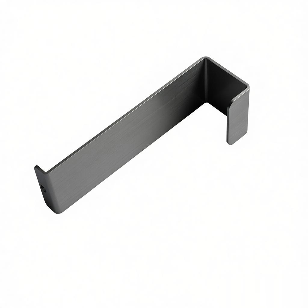
A typical progressive die for a bracket or connector will have 8 to 20 stations. Here is a breakdown of a 12-station example for a stainless steel clip:
| Station # | Operation Type | Function | Dimension Achieved | ----------- | --------------- | ---------- | -------------------- | 1 | Pilot hole piercing | Creates alignment reference | Ø2.00 mm ± 0.01 mm | 2 | Notching | Removes excess material for future bends | 10.0 mm width | 3 | Blanking (partial) | Cuts outer profile except tie points | 25.0 mm length | 4 | Forming (90°) | First bend | Angle 90° ± 0.5° | 5 | Forming (45°) | Pre-form for springback compensation | Angle 45° ± 0.3° | 6 | Coining | Thins material for hinge barrel | Thickness -0.05 mm | 7 | Curling | Forms cylindrical hinge | Ø1.20 mm ± 0.02 mm | 8 | Trimming | Removes tie points from strip | Edge finish < Ra 0.8 µm | 9 | Final forming | Closing bend | Flatness ± 0.05 mm | 10 | Tapping (optional) | Thread forming (if required) | M2.5 x 0.45 | 11 | Sensing | In-die inspection (force or optical) | Rejects > 0.3% | 12 | Cut-off | Separates part from strip | Length tolerance ± 0.05 mm |
|---|
The strip remains connected by a "carrier" (a thin web) until the final cut-off station. This ensures stable feeding and prevents distortion from individual part handling.
3. Material Selection and Thickness Specifications
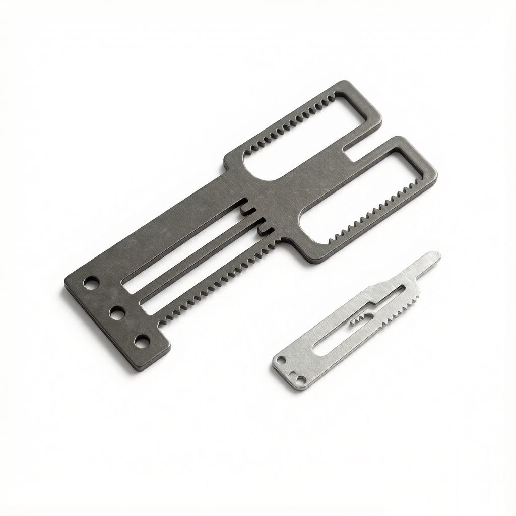
Progressive die stamping works with virtually all ductile metals. The choice affects tool wear, press tonnage, and achievable tolerances. Below is a comparison of common materials used in our Dongguan facility:
| Material | Thickness Range (mm) | Tensile Strength (MPa) | Max Hardness (HRB) | Typical Tolerance (mm) | Relative Cost Index | ---------- | ---------------------- | ------------------------ | -------------------- | ------------------------ | --------------------- | Low Carbon Steel (SPCC) | 0.3 – 4.0 | 270 – 410 | 65 | ± 0.05 | 1.0 | Stainless Steel (SUS304) | 0.2 – 3.0 | 520 – 720 | 90 | ± 0.03 | 2.2 | Aluminum (5052-H32) | 0.5 – 6.0 | 220 – 290 | 45 | ± 0.08 | 1.5 | Copper (C1100) | 0.1 – 2.0 | 200 – 250 | 40 | ± 0.02 | 2.8 | Brass (C2680) | 0.2 – 3.0 | 340 – 480 | 70 | ± 0.03 | 2.5 | Beryllium Copper (C17200) | 0.1 – 1.5 | 1100 – 1380 (heat treated) | 38 (as rolled) | ± 0.01 | 5.0 |
|---|
For high-strength steel (e.g., DP780), tool steel grades like D2 or PM4 (powder metallurgy) are required to withstand abrasive wear. For aluminum, carbide inserts are recommended to prevent galling. The maximum recommended material hardness for standard progressive dies is 45 HRC to avoid premature punch fracture.
4. Cost Analysis: Tooling, Unit Price, and Lead Times
The initial tooling cost for a progressive die is the primary barrier, but it amortizes rapidly with volume. Based on our 2024 production data for a mid-sized part (50 mm x 30 mm x 1.0 mm thick):
| Part Volume (pcs) | Die Cost (USD) | Unit Cost (USD/pc) | Total Cost (USD) | Lead Time for Tooling (weeks) | ------------------- | ---------------- | -------------------- | ------------------ | ------------------------------- | 10,000 | 18,000 | 1.80 | 36,000 | 6 – 8 | 50,000 | 18,000 | 0.55 | 45,500 | 6 – 8 | 100,000 | 18,000 | 0.32 | 50,000 | 6 – 8 | 500,000 | 18,000 | 0.12 | 78,000 | 6 – 8 | 1,000,000 | 18,000 | 0.08 | 98,000 | 6 – 8 |
|---|
As shown, the break-even point is approximately 30,000 pieces when comparing to a multi-slide or stamping-bending cell. For volumes below 5,000 pieces, a multi-slide machine or CNC bending is more economical. Press tonnage for this part is 45 tons, producing at 150 SPM, yielding 9,000 parts per hour without a die sensor rejection rate above 0.2%.
5. Key Advantages and Limitations Compared to Other Forming Methods
Progressive die stamping excels in high-volume production but has constraints. The table below quantifies these contrasts:
| Parameter | Progressive Die | CNC Machining | Sheet Metal Bending (Press Brake) | Metal Injection Molding (MIM) | ----------- | ----------------- | --------------- | ----------------------------------- | ------------------------------- | Production Rate (pcs/min) | 60 – 600 | 0.1 – 5 | 5 – 15 | 5 – 30 | Tolerance (mm) | ± 0.01 – 0.05 | ± 0.005 – 0.02 | ± 0.1 – 0.3 | ± 0.03 – 0.05 | Min. Thickness (mm) | 0.1 | N/A | 0.5 | 0.5 (sintered) | Surface Finish (Ra µm) | 0.4 – 1.6 | 0.2 – 0.8 | 0.8 – 3.2 | 0.8 – 1.6 | Tooling Cost (USD) | 10k – 100k | 0 (no tooling) | 1k – 5k | 15k – 60k | Unit Cost at 100k pcs | Very Low | Very High | High | Medium | Max Part Complexity | High (multi-axis bends) | Very High (3D) | Low (simple bends) | High (3D, but limited size) | Material Waste | 15% – 25% | 40% – 60% | 10% – 15% | 2% – 5% (but high energy) |
|---|
For heat sinks, our primary product line, progressive stamping is ideal for folded-fin arrays (0.2 mm aluminum) because it achieves a fin density of 10 fins per cm with a height-to-thickness ratio of 40:1, which is impossible with extrusion.
6. Practical Engineering Recommendations and FAQ-Style Tips
**Tip 1: Design for progressive die (DFM).** Avoid sharp corners; use a minimum fillet radius of 0.5x material thickness to prevent punch cracking. For bends, maintain a minimum bend radius of 1x thickness for mild steel and 2x for aluminum.
**Tip 2: Springback compensation.** For stainless steel, overbend by 2° to 3° per 90° bend. For aluminum 5052, expect 1° to 1.5° springback. Use coining (thickness reduction of 10%) to stabilize dimensions.
**Tip 3: Pilot holes.** Always include at least one pilot hole of Ø2.0 mm or larger. The pilot hole's diameter should be 0.05 mm smaller than the pilot pin to allow for slight misalignment without deformation.
**Tip 4: Burr direction.** Specify the burr side (punch entry side) in your drawing. Burrs typically measure 5% to 10% of material thickness. If burr-free edges are required, add a secondary deburring operation or use a fine-blanking process.
**Tip 5: Heat generation.** At 300 SPM, die temperature rises to 40°C – 60°C. Use a high-viscosity lubricant (e.g., 20 cSt at 40°C) for stainless steel to prevent galling. For aluminum, use a low-viscosity oil (10 cSt) to avoid staining.
**Tip 6: Tolerances vs. cost.** For every 0.01 mm reduction in tolerance below ±0.05 mm, tooling cost increases by 15% and maintenance frequency doubles. Only specify tight tolerances on critical mating features.
Conclusion: When to Choose Progressive Die Stamping
Select progressive die stamping when your annual volume exceeds 50,000 units, part weight is under 2 kg, and material thickness is between 0.1 mm and 6.0 mm. It offers the lowest cost per piece, highest repeatability, and shortest cycle times among all metal forming methods. At BQUQ, we have run progressive dies for 20 years, producing heat sinks, springs, and precision brackets with tolerances down to ±0.01 mm. Our engineers provide DFM feedback within 24 hours, ensuring your design is optimized for tool longevity and material yield.
For an immediate cost estimate on your stamped component, send us your 2D drawing or 3D model. We respond with a full tooling and unit price quote within 12 hours. Contact us at **Email: sc@bquq.com** or **WhatsApp: +86 13713157787**. Visit our website at **www.bquq.com** to view case studies and download our design guidelines.
Related Articles
- Stamping Press Selection Guide 2024: Mechanical vs Hydraulic vs Servo Speed and Force
- 5 Effective Burr Removal Techniques for Stamped Parts
- Stamping Lubricant Selection 2024: Balancing Die Life, Part Quality, and Environmental Compliance
Frequently Asked Questions
What is the minimum tolerance achievable with progressive die stamping?
Progressive die stamping can achieve tolerances as tight as ±0.01 mm for finished parts. Positional accuracy relative to the first station can be maintained within ±0.005 mm using pilot pins. Feed accuracy is ±0.02 mm at 600 strokes per minute with servo roll feeders.
What material thicknesses can be processed in progressive die stamping?
Progressive die stamping can process metal strips ranging from 0.1 mm to 6.0 mm thick. The minimum hole size is 0.5 times the material thickness for mild steel. Material utilization typically ranges from 60% to 80% with optimized nesting.
What production volumes are most cost-effective for progressive die stamping?
Progressive die stamping is most cost-effective for high volumes, typically 50,000 or more parts. The process yields one finished part per press cycle, with stroke rates ranging from 30 to 1,200 strokes per minute depending on part size and material.
How long does a progressive die last before needing maintenance?
A standard progressive die with carbide inserts can last 1 to 5 million strokes before regrinding is required. Die life depends on material type, part complexity, and maintenance practices. In-die sensing systems can reject parts with defects exceeding 0.3%.