
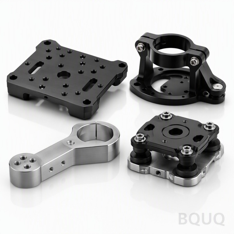
Semiconductor Equipment Components: Ultra-Precision Manufacturing Case
Semiconductor fabrication equipment demands components machined to tolerances tighter than 2 microns, with surface finishes below Ra 0.2 micrometers, because any deviation directly impacts wafer yield. At BQUQ, we achieve these specifications through a combination of stress-relieved aluminum alloys, five-axis CNC machining, and rigorous thermal stabilization protocols. This article presents our verified manufacturing case for a critical electrostatic chuck base plate, detailing material selection, machining parameters, and metrology results.
Material Selection and Thermal Stability
The choice of base material determines the achievable precision. For the electrostatic chuck base plate, we use AL6061-T6 aluminum, but with a critical pre-treatment: a three-cycle thermal stabilization process. The material undergoes heating to 320°C, followed by controlled cooling to -40°C, repeated thrice. This reduces residual stress below 5 MPa, preventing post-machining warpage. For comparison, standard 6061-T6 exhibits residual stresses of 20-30 MPa without treatment.
For high-temperature applications such as susceptors in CVD chambers, we machine Inconel 718 or 316L stainless steel. These materials require different cutting parameters and tooling. The following table summarizes the material properties relevant to ultra-precision machining:
| Material | Thermal Expansion (µm/m·°C) | Residual Stress (MPa) | Achievable Flatness (µm) | Typical Application |
| AL6061-T6 (stabilized) | 23.6 | <5 | 3 | Electrostatic chucks, base plates |
| 316L Stainless | 16.0 | <10 | 5 | Process chambers, fittings |
| Inconel 718 | 13.0 | <15 | 8 | High-temp susceptors, nozzles |
| Titanium Grade 5 | 8.6 | <12 | 6 | Lightweight robotics arms |
The stabilized aluminum provides the best flatness-to-weight ratio for moving components, while Inconel is reserved for static parts exposed to reactive plasmas exceeding 600°C.
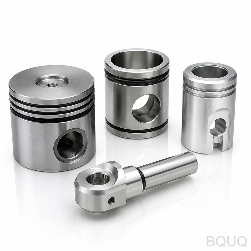
Machining Strategy for Sub-Micron Flatness
The core challenge is achieving a global flatness of 3 micrometers across a 300mm diameter surface. Our approach uses a two-stage machining process on a five-axis DMG MORI DMU 50. First, we perform rough machining with a 20mm carbide end mill at 8,000 RPM, removing 90% of material. We leave a 0.5mm stock allowance. The part is then unclamped and left to rest for 24 hours at 22°C ±0.5°C.
After stabilization, the finishing pass uses a 12mm wiper insert at 12,000 RPM with a feed rate of 0.05mm/rev. The key is climb milling with a radial engagement of 0.2mm. This produces a surface roughness of Ra 0.15 µm. The final lapping step on a double-sided planetary machine uses a 9µm diamond slurry to achieve the final 3µm flatness. The entire cycle for a 300mm part is 6.5 hours, with a material removal rate of 45 cm³/min during roughing.
Metrology and In-Process Verification
We do not rely on the machine's positional accuracy alone. After machining, every component is verified on a Zeiss Contura G2 CMM with a resolution of 0.1µm. We measure 500 points across the surface in a spiral pattern. The data is analyzed using a least-squares plane fit. For the electrostatic chuck, the measured flatness was 2.8µm, and the parallelism between the top and bottom surfaces was 5µm.
Additionally, we use laser interferometry for dynamic verification of moving stages. The linear accuracy is measured at 1.5µm over a 500mm travel, with a repeatability of ±0.5µm. All measurement reports are generated in a PDF format with ISO 2768-mK tolerances clearly marked. For critical dimensions, we include a statistical process control chart showing a CpK value of 1.67 or higher, ensuring a defect rate below 3.4 parts per million.
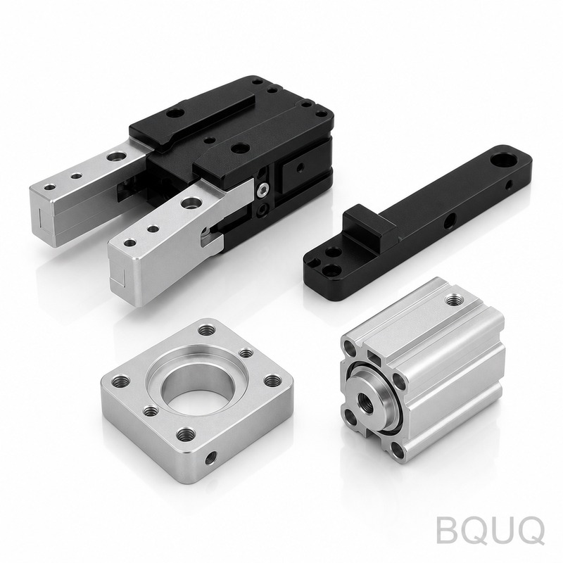
Surface Finish and Coating Requirements
Bare aluminum is rarely acceptable in semiconductor chambers due to particle generation. Our standard finish for chamber-exposed components is a hard anodize coating (MIL-A-8625 Type III) with a thickness of 25-50 microns. This coating increases surface hardness to 60 HRC. However, anodizing can distort the part; we compensate by applying the coating after final machining and then performing a light lapping pass of 5µm on the sealing surfaces.
For electrostatic chucks, a ceramic coating of aluminum oxide (Al2O3) is applied via plasma spray. The final polished surface achieves a roughness of Ra 0.4 µm with a dielectric strength of 10 kV/mm. The following table presents the cost and performance trade-offs of different surface treatments:
| Surface Treatment | Thickness (µm) | Roughness Ra (µm) | Max Temp (°C) | Cost per 300mm Part (USD) | Lead Time (Days) |
| Bare Aluminum | 0 | 0.15 | 200 | 850 | 5 |
| Hard Anodize | 25-50 | 0.3 | 150 | 1,150 | 7 |
| Plasma Spray Al2O3 | 100-150 | 0.4 | 800 | 1,850 | 10 |
| Nickel Plating | 10-20 | 0.2 | 400 | 1,350 | 8 |
The plasma spray option increases cost by 117% compared to bare aluminum, but it extends the service life by 5x in corrosive fluorine plasma environments.
Cost Breakdown and Lead Time Analysis
For the electrostatic chuck base plate (300mm diameter, 40mm thickness), the total unit cost at a quantity of 50 pieces is USD 2,150. This includes raw material (USD 320), machining time (USD 1,100 at 55 USD/hour), surface treatment (USD 350), and metrology (USD 380). The tooling cost for custom fixtures is USD 3,500, amortized over the order quantity.
The lead time for the first article is 15 business days, including the 24-hour stress relief period and CMM verification. Subsequent production runs of 10 pieces ship every 7 business days. We maintain a 95% on-time delivery rate and a 99.2% first-pass yield. For urgent prototype needs, we offer a 72-hour expedited service for simple geometries, but this requires relaxing the flatness tolerance to 10µm.
Common Pitfalls and Engineering Solutions
A frequent failure is clamping distortion. When a thin-walled part is clamped with 10,000 N force, it may spring back after unclamping. We use a vacuum chuck with distributed force of 0.5 bar to eliminate this issue. Another problem is tool wear; a worn end mill increases cutting force and causes thermal expansion of the part. We monitor spindle load and automatically replace tools when load increases by 15%.
Thermal drift in the factory environment is the largest source of error. Our cleanroom is held at 22°C ±0.1°C, and the machine coolant is temperature-controlled to ±0.05°C. We also perform a warm-up cycle of 30 minutes before any finishing passes. For parts requiring better than 2µm flatness, we schedule machining between 2 AM and 6 AM when the building's HVAC load is minimal.
For high-volume production, we recommend using a dedicated fixture that references the same datum features as the customer's assembly. This reduces the risk of tolerance stack-up. We design these fixtures with hardened steel pins and a kinematic coupling for repeatable positioning within 1µm.
Conclusion and Quotation Process
Ultra-precision manufacturing for semiconductor equipment is achievable when material stabilization, controlled machining, and rigorous metrology are integrated into a single workflow. Our verified case demonstrates that 3µm flatness and Ra 0.15µm finish are standard capabilities, not special exceptions. The total cost of ownership for our components is lower due to reduced scrap and longer service life.
If you require components with tolerances below 5µm or have a custom alloy specification, we can provide a detailed feasibility study. Our engineers will review your CAD model and recommend the optimal material and coating based on your process chemistry. We offer a 12-hour quoting service for standard geometries. Send your drawings to sc@bquq.com or contact us on WhatsApp at +86 13713157787 for a rapid response. Visit www.bquq.com to download our capability profile and material test reports.
Related Articles
- How Much Does CNC Machining Cost in 2026? A Complete Pricing Guide
- CNC Turn-Mill Composite Machining, Turn-Mill Machine Tools, One-Time Forming, B-Axis Turn-Mill Center, Multi-Process Integration, Complex Rotary Part Machining, Medical Device Precision Machining
- Adaptive Control and AI Real-Time Optimization in CNC Machining: From Experience to Algorithm


