
Learn effective thermal management for high brightness LEDs with custom heat sinks. Design tips and manufacturing techniques for optimal heat dissipation.
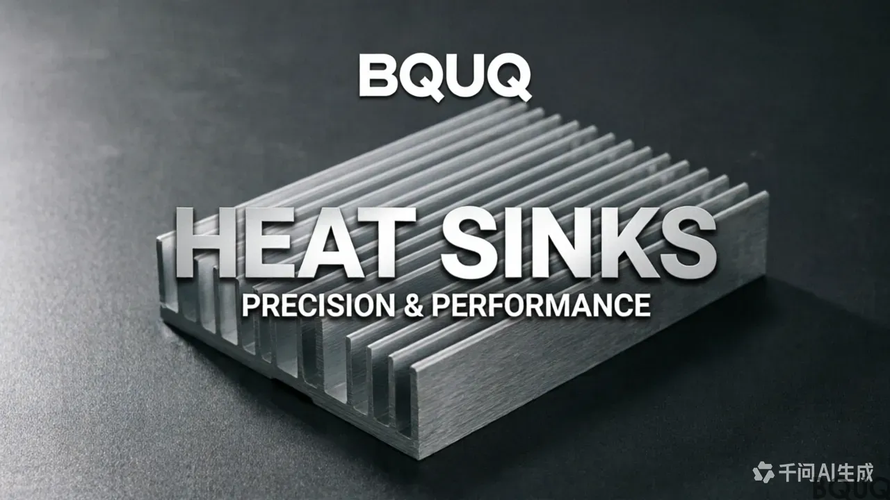
Thermal Management for High Brightness LEDs with Heat Sinks
High brightness LEDs (HB LEDs) are revolutionizing lighting, automotive, and display industries with their efficiency and longevity. However, their superior performance generates significant heat, which if not managed properly, can lead to reduced lifespan, color shift, and catastrophic failure. Effective thermal management is paramount, and heat sinks are the most common solution. This guide dives deep into the principles, design, materials, and manufacturing of heat sinks tailored for high brightness LEDs, ensuring optimal performance and reliability.
Understanding Thermal Management in High Brightness LEDs
LEDs convert only about 20-30% of electrical energy into light; the rest becomes heat. In HB LEDs, the heat flux can exceed 100 W/cm² at the chip level. This concentrated heat must be dissipated efficiently to maintain junction temperatures below manufacturer specifications (typically 85-125°C). Thermal management involves a pathway from the LED junction through the package, PCB, thermal interface materials (TIMs), and finally the heat sink to the ambient air.
The Thermal Pathway
Junction to Case: Heat moves from the LED chip to its substrate.
Case to PCB: Often via thermal pads or solder.
PCB to Heat Sink: Through TIM (grease, pads, or phase change materials).
Heat Sink to Ambient: Convection and radiation.
Each interface adds thermal resistance (Rth). The total Rth must be minimized to keep the junction temperature (Tj) low. A rule of thumb: for every 10°C reduction in Tj, LED lifetime doubles.
Why Heat Sinks Are Essential for LED Performance
Heat sinks increase the surface area for convective heat transfer, lowering the thermal resistance from device to air. Without a heat sink, a bare LED mounted on a PCB can only dissipate a few watts. With an optimized heat sink, HB LEDs can handle tens of watts. Key benefits include:
Enhanced Lumen Maintenance: Consistent light output over time.
Color Stability: Reduced wavelength shift due to temperature changes.
Increased Lifespan: Prevents premature failure from thermal stress.
Higher Current Capacity: Enables brighter operation within safe thermal limits.
Key Design Considerations for LED Heat Sinks
Thermal Resistance Target
Calculate the required heat sink thermal resistance (Rth_sink) using: Rth_sink = (Tj_max - Ta) / P - Rth_jc - Rth_pcb - Rth_tim. Where Ta is ambient temperature, P is power dissipation. For example, if Tj_max=125°C, Ta=50°C, P=10W, and other resistances sum to 3°C/W, then Rth_sink must be ≤ (75/10) - 3 = 4.5°C/W.
Geometry and Surface Area
Fins increase surface area. Common shapes include:
| Fin Type | Advantages | Disadvantages |
|---|---|---|
| Straight rectangular | Easy to manufacture, good for natural convection | Less efficient in forced convection |
| Pin fin | High surface area, omni-directional cooling | Higher pressure drop, more costly |
| Flared or angled | Enhanced airflow guidance | Complex tooling |
Material Selection
Aluminum (alloy 6063 or 6061) is common due to high thermal conductivity (~200 W/m·K) and low cost. Copper (~400 W/m·K) offers better performance but is heavier and more expensive. Our company provides both options, with precision CNC machining for high tolerance applications.
Mounting and Interface
Ensure flat mating surfaces to minimize TIM thickness. Use screws with spring washers to maintain consistent pressure. A gap of
Frequently Asked Questions
What is the typical heat flux at the chip level for high brightness LEDs, and why does it matter for heat sink design?
The heat flux at the chip level can exceed 100 W/cm². This concentrated heat must be dissipated efficiently to keep junction temperatures below manufacturer specs (typically 85-125°C). This high flux drives the need for optimized heat sink geometry and materials to minimize thermal resistance along the entire pathway.
How do I calculate the required thermal resistance for a heat sink in an LED application?
Use the formula: Rth_sink = (Tj_max - Ta) / P - Rth_jc - Rth_pcb - Rth_tim. For example, if Tj_max=125°C, Ta=50°C, P=10W, and other resistances sum to 3°C/W, then Rth_sink must be ≤ (75/10) - 3 = 4.5°C/W. This ensures the junction temperature stays within safe limits.
What are the key benefits of using a heat sink for high brightness LEDs?
Heat sinks enhance lumen maintenance, ensuring consistent light output over time. They also provide color stability by reducing wavelength shift, increase lifespan by preventing thermal stress failure, and enable higher current capacity for brighter operation within safe thermal limits. Without one, a bare LED can only dissipate a few watts.
What is the rule of thumb regarding LED junction temperature and lifetime?
For every 10°C reduction in junction temperature (Tj), LED lifetime doubles. This makes minimizing total thermal resistance (Rth) across the junction-to-case, case-to-PCB, PCB-to-heat sink, and heat sink-to-ambient pathway critical for maximizing the operational life of high brightness LEDs.


