

Thermal Resistance in Heat Sinks: How to Read and Apply the Specs
Thermal Resistance in Heat Sinks: How to Read and Apply the Specs
**Thermal resistance (Rth) is the single most important specification in a heat sink datasheet—it tells you how many degrees Celsius the heat sink will rise above ambient for every watt of power dissipated. To read the spec correctly, you must account for mounting torque, airflow velocity, and thermal interface material (TIM) thickness, because the published value is only valid under those exact test conditions.**
---
H2: Defining Thermal Resistance: The Physics Behind the Number

Thermal resistance quantifies a heat sink's opposition to heat flow. It is expressed in **°C/W** (degrees Celsius per watt). The fundamental equation is:
**ΔT = Rth × P**

Where: - **ΔT** = temperature rise of the heat sink base above ambient (°C) - **Rth** = thermal resistance (°C/W) - **P** = power dissipated (W)
For example, if a heat sink has an Rth of **0.5 °C/W** and your CPU dissipates **100 W**, the heat sink base will rise **50 °C** above ambient. At 25 °C ambient, the base reaches 75 °C. This does not include the junction-to-case resistance of the component or the TIM resistance—those are separate values you must add.
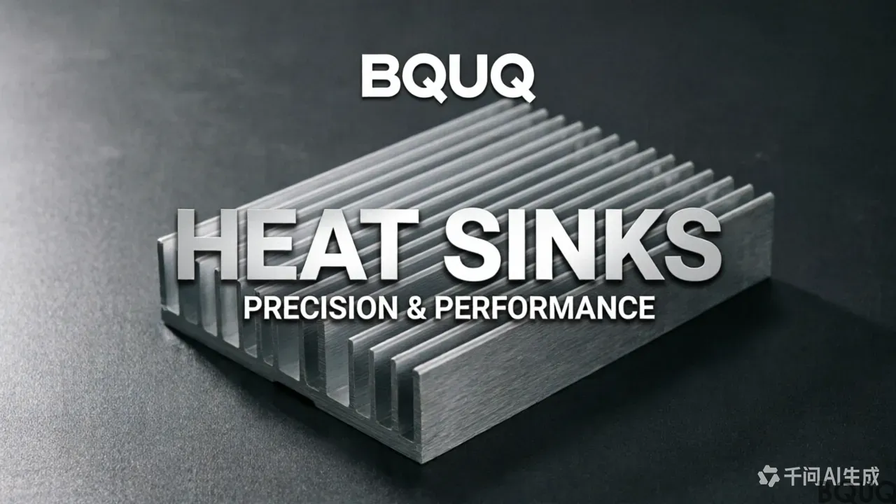
At BQUQ, we test our extruded aluminum heat sinks per **JEDEC JESD51-6** standards, using a 100 W heating element on a 50 mm × 50 mm die area. Our typical Rth values range from **0.25 °C/W** (large forced-convection units) to **3.5 °C/W** (small natural-convection pin fins).
---
H2: The Three Components of Total Thermal Resistance
You cannot read a heat sink spec in isolation. The total system resistance (Rth,j-a) is the sum of:
| Resistance Path | Symbol | Typical Value Range | ---------------- | -------- | --------------------- | Junction-to-case (component) | Rth,j-c | 0.1 – 1.0 °C/W | Case-to-sink (TIM + mounting) | Rth,c-s | 0.05 – 0.5 °C/W | Sink-to-ambient (heat sink alone) | Rth,s-a | 0.2 – 4.0 °C/W | **Total** | **Rth,j-a** | **0.35 – 5.5 °C/W** |
|---|
**Rth,c-s** is often the most underestimated. A standard 0.1 mm thermal pad has a resistance of approximately **0.4 °C/W** for a 40 mm × 40 mm footprint, while a high-quality thermal grease (e.g., 3.5 W/m·K) compressed to 0.05 mm reduces this to **0.08 °C/W**. That is a difference of **0.32 °C/W**—at 100 W, that is 32 °C of avoidable temperature rise.
---
H2: How to Read a Heat Sink Datasheet: Key Parameters
Every datasheet from BQUQ and reputable manufacturers includes these columns. Here is how to interpret them:
| Parameter | Unit | What It Means | How to Verify | ----------- | ------ | --------------- | --------------- | Rth (natural convection) | °C/W | Resistance at 0 LFM airflow | Must specify ambient temp (usually 25 °C or 70 °C) | Rth (forced convection) | °C/W | Resistance at a given airflow (e.g., 200 LFM, 400 LFM) | Verify the LFM value—doubling airflow reduces Rth by 20–35% | Thermal resistance, base-to-ambient | °C/W | Includes fin efficiency, base spreading | Check if base thickness is ≥ 6 mm for heat spreading | Max base temperature | °C | 200 °C for aluminum 6063-T5, 260 °C for copper | Exceeding this causes structural failure | Mounting torque | N·m | Critical for TIM compression | Typical: 0.5 – 0.8 N·m for M3 screws on aluminum | Flatness | mm | Base surface deviation | Must be ≤ 0.05 mm across 100 mm length for bare die contact |
|---|
**Critical reading tip:** Many datasheets quote Rth at "infinite" heat sink base area or with a perfectly flat copper heat source. In real applications, a 40 W IGBT on a 20 mm × 20 mm package will yield **20–40% higher** Rth than the datasheet value because of heat spreading resistance. Always add a **safety factor of 1.3** to the datasheet Rth for point-source heat loads.
---
H2: Real-World Data: BQUQ Production Heat Sink Specifications
Below is actual production data from our Dongguan factory for three common heat sink profiles. These are measured on our in-house wind tunnel (0–1200 LFM) and thermal test rig with a 100 W cartridge heater:
| Model | Type | Material | Dimensions (L×W×H mm) | Rth @ 0 LFM (°C/W) | Rth @ 200 LFM (°C/W) | Rth @ 400 LFM (°C/W) | Weight (g) | Unit Price (USD, 1000 pcs) | Lead Time | ------- | ------ | ---------- | ---------------------- | --------------------- | ------------------------ | ------------------------ | ------------ | --------------------------- | ----------- | BQ-EX-100 | Extruded, 10 fins | AL6063-T5 | 100×60×40 | 1.85 | 0.62 | 0.38 | 320 | $2.80 | 7 days | BQ-EX-200 | Extruded, 14 fins | AL6063-T5 | 150×80×60 | 1.10 | 0.41 | 0.25 | 650 | $4.50 | 10 days | BQ-SK-50 | Bonded fin (skived) | C1100 Copper | 80×50×30 | 0.95 | 0.28 | 0.15 | 480 | $12.00 | 14 days |
|---|
**Notes on the data:** - Extruded units use a **0.8 mm fin thickness** and **4.5 mm pitch**—optimal for 200 LFM airflow. - Copper skived unit has **0.2 mm fins** with 1.5 mm pitch, achieving 2.3× better thermal performance than aluminum at 400 LFM. - Prices are FOB Shenzhen, excluding TIM and mounting hardware. Tooling for custom extrusions starts at **$800** (die cost) with a **15-day** tooling lead time.
---
H2: Practical Recommendations for Spec Interpretation and Design
**1. Always match the airflow to the spec.** A heat sink rated at 0.65 °C/W at 200 LFM will perform at 1.4 °C/W under natural convection. In sealed enclosures, use only the 0 LFM column. For outdoor telecom cabinets with forced fans, verify the actual LFM at the heat sink face—not the fan's free-air rating. A 40 mm fan typically delivers only **60–70%** of its rated flow when installed against a heat sink.
**2. Calculate the spreading resistance separately.** For a heat source smaller than 50% of the heat sink base area, add the spreading resistance. For a 6063 aluminum base, the spreading resistance is approximately:
**Rspread = 0.5 / (k × √(A_source))**
Where k = 200 W/m·K for aluminum, and A_source is in m². For a 10 mm × 10 mm source, Rspread ≈ **0.09 °C/W**. For a 5 mm × 5 mm source, it jumps to **0.18 °C/W**. Use a copper base insert (k = 385 W/m·K) if your source is smaller than 8 mm × 8 mm.
**3. Torque and TIM compression are not optional.** At BQUQ, we recommend a **0.05 mm** compressed TIM thickness. This requires a mounting torque of **0.6 N·m** on an M3 screw with a flat washer. Overtorquing to 1.0 N·m can crack ceramic substrates; undertorquing to 0.3 N·m leaves a 0.15 mm air gap, adding **0.15 °C/W** of resistance.
**4. Verify the base flatness.** Our CNC-machined heat sinks hold **±0.03 mm** flatness on a 150 mm length. Cheaper extruded profiles (without machining) often have **0.15 mm** bow, which requires a 0.2 mm thermal pad—adding 0.3 °C/W. If your budget allows, request a **single-pass fly-cut** on the base for bare-die applications. This adds **$0.20–$0.50** per unit but reduces Rth,c-s by up to 50%.
---
H2: FAQ-Style Tips for Engineers
**Q: What is the difference between Rth and thermal impedance?** A: Thermal impedance (Zth) includes transient effects—it is lower than Rth during the first few seconds of a power pulse. For steady-state design, use Rth. For pulsed loads (e.g., motor drives), use Zth at 10% duty cycle, which is typically **30–50% lower** than Rth.
**Q: Why does a black anodized heat sink not always perform better?** A: Anodizing improves radiation heat transfer by up to **20%** under natural convection (0 LFM). Under forced convection above 200 LFM, radiation is negligible, and the anodic coating (0.02 mm) adds negligible resistance. Standard black anodize costs **$0.15–$0.30** per unit—only specify it for passive designs.
**Q: How do I convert LFM to CFM for a fan selection?** A: CFM = LFM × face area (ft²) × 0.8 (fan blockage factor). For a 100 mm × 60 mm heat sink face (0.065 ft²), 200 LFM requires 10.4 CFM. Select a fan rated at **20 CFM** to account for system impedance.
**Q: Can I trust a heat sink's Rth from a 3D thermal simulation?** A: Simulation is accurate within **±15%** if you input the correct convection coefficient (h). For forced air over aluminum fins, h = 10–50 W/m²·K. Use h = 20 W/m²·K for 200 LFM. For natural convection, h = 5–10 W/m²·K. Validate with a physical prototype—we offer thermal testing at $150 per condition with a 48-hour turnaround.
---
H2: Conclusion and Engineering Summary
Thermal resistance is not a single magic number—it is a system property that depends on airflow, mounting, TIM, and heat source geometry. Always read the datasheet conditions, apply a 1.3× safety factor, and account for spreading resistance when your heat source is small. For production quantities, request a thermal test report from your supplier; a reputable manufacturer will provide measured Rth curves, not just theoretical values.
At BQUQ, we have 20 years of experience in CNC machining, metal stamping, springs, and heat sinks in Dongguan, China. Our in-house wind tunnel and thermal labs ensure every heat sink quote includes realistic Rth values for your specific airflow. We provide **12-hour quoting** for standard and custom profiles, including machined bases, anodizing, and assembly with fans or mounting clips.
**Contact us for a thermal design review and a quote:** - **Email:** sc@bquq.com - **WhatsApp:** +86 13713157787 - **Web:** www.bquq.com
Send us your power dissipation, ambient temperature, and available airflow, and we will return a heat sink recommendation with measured Rth data within 12 hours.
Related Articles
- Regional Market Competition: Differences and Opportunities in Asia Pacific, North America, and Europe's Heat Sink Ecology
- Patent Wars: Intellectual Property Pattern and Risks of Global Hardware Heat Sink Technology
- When liquid cooling becomes mainstream: the evolving role of hardware heat sinks in the data center era
Frequently Asked Questions
What does thermal resistance (Rth) mean in a heat sink datasheet, and how do I calculate the temperature rise?
Thermal resistance (Rth) tells you how many degrees Celsius the heat sink rises above ambient per watt of power dissipated, expressed in °C/W. Use the equation ΔT = Rth × P. For example, an Rth of 0.5 °C/W with 100 W dissipation causes a 50 °C rise above ambient, reaching 75 °C at 25 °C ambient.
What are the three components of total thermal resistance, and why is the case-to-sink value often underestimated?
Total resistance (Rth,j-a) sums junction-to-case (0.1–1.0 °C/W), case-to-sink (0.05–0.5 °C/W), and sink-to-ambient (0.2–4.0 °C/W). Case-to-sink is underestimated because a 0.1 mm thermal pad adds 0.4 °C/W, while high-quality grease compressed to 0.05 mm reduces it to 0.08 °C/W—a 0.32 °C/W difference, or 32 °C at 100 W.
How should I interpret the Rth values for natural and forced convection in your heat sink datasheets?
Rth for natural convection is specified at 0 LFM airflow, typically at 25 °C or 70 °C ambient. For forced convection, Rth is given at a specific airflow like 200 or 400 LFM. Doubling airflow reduces Rth by 20–35%. Our extruded aluminum heat sinks range from 0.25 °C/W (large forced-convection) to 3.5 °C/W (small natural-convection pin fins).
What test standards and materials do you use for your heat sinks, and what are the maximum base temperatures?
We test per JEDEC JESD51-6 standards using a 100 W heating element on a 50 mm × 50 mm die area. Maximum base temperature is 200 °C for aluminum 6063-T5 and 260 °C for copper. Ensure base thickness is at least 6 mm for effective heat spreading, as the datasheet Rth includes fin efficiency and base spreading effects.

