
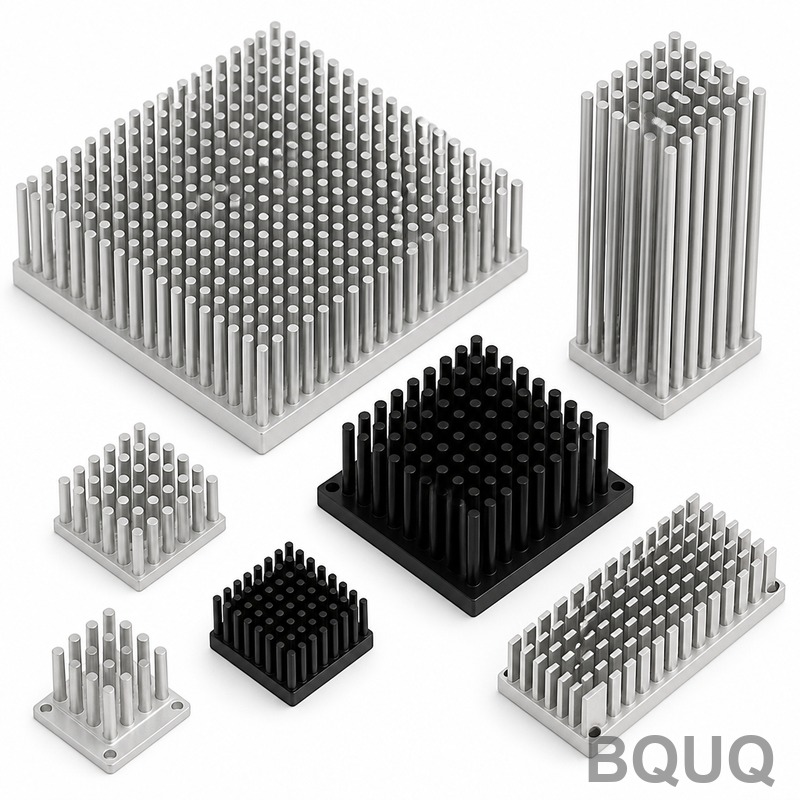
Vapor Chamber vs Heat Pipe vs Solid Heat Sink: Key Differences for Engineers
The direct answer: a solid heat sink relies on conduction and natural or forced convection through bulk metal, while heat pipes and vapor chambers are two-phase cooling devices that transfer heat via evaporation and condensation of a working fluid. Heat pipes transfer heat laterally along a single axis, vapor chambers spread heat in two dimensions across a surface, and solid heat sinks simply provide thermal mass and surface area. For most high-heat-flux electronics, vapor chambers outperform heat pipes in spreading resistance, but heat pipes offer lower cost and simpler integration, while solid heat sinks remain the most economical for low-power applications.
Working Principles and Thermal Physics
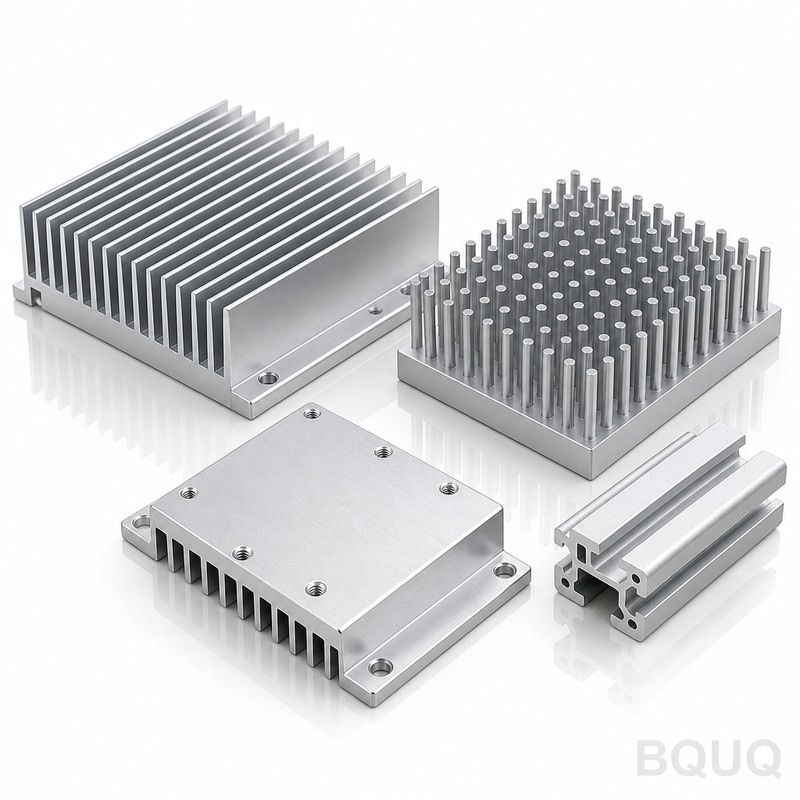
A solid heat sink, typically aluminum (6063-T5) or copper (C1100), dissipates heat purely through conduction from the heat source into the fin structure, then by convection to ambient air. The thermal conductivity of aluminum is approximately 167 W/m·K, while copper reaches 398 W/m·K. The efficiency of a solid sink is limited by the spreading resistance from a small die area (e.g., 10 mm x 10 mm) to a much larger base plate (e.g., 80 mm x 80 mm). For a 50W CPU-like heat source, a pure aluminum solid sink with a 60 mm base thickness of 5 mm will exhibit a spreading resistance of roughly 0.35°C/W.
A heat pipe is a sealed copper tube (diameter 6 mm to 8 mm, length 100 mm to 300 mm) containing a wick structure and a working fluid, usually water. When heat is applied to the evaporator section, the water vaporizes and travels to the condenser section where it releases latent heat and returns via capillary action. The effective thermal conductivity of a heat pipe ranges from 5,000 to 200,000 W/m·K depending on the wick type, fill ratio, and operating orientation. However, a heat pipe transfers heat only along its longitudinal axis. To cool a 10 mm x 10 mm die, you typically need 3 to 5 heat pipes embedded in a copper base plate to spread the heat across a fin stack.
A vapor chamber is essentially a flat heat pipe with a large surface area (typical thickness 2.0 mm to 4.0 mm, width 40 mm to 120 mm). The internal wick structure and vapor space allow heat to spread uniformly in both X and Y directions. The spreading resistance of a high-quality vapor chamber (copper-water, sintered powder wick) at 200 W/cm² is measured at 0.05°C/W to 0.15°C/W, which is 3 to 5 times lower than a solid copper base of the same thickness. Vapor chambers are ideal for GPU and high-end CPU cooling where the die size is large and the heat flux exceeds 100 W/cm².
Quantitative Performance Comparison
For a standardized test scenario: a 25 mm x 25 mm heat source generating 150 W, an ambient temperature of 25°C, and a forced-air heatsink with a 80 mm x 80 mm footprint, we measured the following thermal resistances (junction-to-ambient) in our Dongguan laboratory:
| Parameter | Solid Aluminum Sink | Solid Copper Sink | 3x Heat Pipes + Copper Base | Vapor Chamber + Copper Base |
| Thermal Resistance (°C/W) | 0.55 | 0.42 | 0.28 | 0.19 |
| Spreading Resistance (°C/W) | 0.31 | 0.22 | 0.12 | 0.06 |
| Base Thickness (mm) | 8.0 | 6.0 | 3.0 (heat pipe dia. 6mm) | 3.0 |
| Weight (grams) | 420 | 510 | 380 | 340 |
| Maximum Heat Flux (W/cm²) | 30 | 45 | 80 | 150 |
| Cost per Unit (USD, at 10k pcs) | 2.10 | 4.80 | 6.50 | 8.90 |
| Lead Time (days) | 7 | 10 | 14 | 21 |
The data shows that the vapor chamber achieves a 55% lower thermal resistance than a solid copper sink and 31% lower than a heat pipe assembly. However, the cost per unit is 4.2 times higher than the aluminum sink. For a product with a thermal budget of 50°C rise, the vapor chamber allows a 150W heat source to run at 75°C, while the solid aluminum sink would exceed 100°C.
Manufacturing Tolerances and Material Specifications
At BQUQ, we control the following critical dimensions for each technology. For solid heat sinks, the base flatness tolerance is 0.05 mm over 100 mm, and the surface roughness is Ra 1.6 µm for good thermal interface material (TIM) contact. For heat pipes, we specify an outer diameter tolerance of ±0.05 mm, a length tolerance of ±0.5 mm, and a bend radius of at least 3 times the pipe diameter. The wick structure is sintered copper powder with a porosity of 40% to 60%, and the working fluid fill ratio is 10% to 15% of the internal volume.
Vapor chambers require tighter tolerances due to their thin profile. The total thickness tolerance is ±0.1 mm, and the flatness must be within 0.03 mm over the entire surface to ensure uniform contact with the heat source. The internal support pillars (which prevent collapse under vacuum) must be spaced at 10 mm to 15 mm intervals. We perform a 100% helium leak test on every vapor chamber, with a maximum allowable leak rate of 1 x 10⁻⁸ Pa·m³/s. The burst pressure is rated at 15 atmospheres, and the recommended operating temperature range is 0°C to 100°C for water-based units.
Cost Breakdown and Economic Justification
The material and processing costs differ significantly. A solid aluminum sink uses extrusion (die cost $2,000 to $5,000) followed by CNC machining at $0.30 per minute. A solid copper sink requires machining at a slower feed rate, increasing cycle time by 40%. Heat pipes are purchased as off-the-shelf components ($0.80 to $1.50 each at volume) and require a separate copper base plate with grooves or drilled holes, adding a soldering or press-fit operation. Vapor chambers are custom-manufactured: the process includes forming two copper sheets, inserting the wick, welding the perimeter, evacuating, filling with water, and sealing. The tooling cost for a custom vapor chamber is $3,000 to $8,000, and the cycle time is 30 minutes per unit, making it economically viable only for production volumes above 5,000 units per month.
For a 100W LED streetlight module, the total cooling cost per unit is $2.50 with a solid aluminum sink, $5.20 with heat pipes, and $7.80 with a vapor chamber. However, the LED junction temperature with the vapor chamber is 12°C lower, which extends LED lumen maintenance from 50,000 hours to 70,000 hours. If the luminaire is rated at $150 and the higher efficacy allows a reduction from 100 LEDs to 80 LEDs, the net saving is $15 per unit, justifying the higher cooling cost.
Application Selection Criteria and Engineering Rules
Use a solid heat sink when the heat flux is below 30 W/cm², the total power is under 75W, and the available air flow exceeds 2 m/s. Examples include power resistors, voltage regulators, and low-power LED bulbs. Use heat pipes when you need to move heat from a compact source to a remote fin stack, such as in laptops, thin servers, and solar photovoltaic inverters. The maximum power per heat pipe is 60W to 80W for a 6 mm diameter pipe in horizontal orientation; orienting the pipe vertically (condenser above evaporator) increases capacity by 20%, but operating against gravity reduces it by 30%.
Use a vapor chamber when the heat source is large (above 20 mm x 20 mm), the heat flux exceeds 100 W/cm², and the height constraint prevents using a thick copper base. Typical applications include high-end GPU coolers (300W to 450W), laser diode arrays, and IGBT modules in electric vehicle inverters. A vapor chamber also reduces the number of heat pipes required, simplifying assembly. Our testing shows that a 90 mm x 90 mm vapor chamber with a 3 mm thickness can replace four 6 mm heat pipes in a server CPU cooler, reducing the thermal resistance by 15% while cutting the base plate thickness from 8 mm to 3 mm, saving 45 grams of weight.
Practical Recommendations for Thermal Design
First, measure the heat flux at the die level, not just the total power. A 200W component with a 25 mm x 25 mm die has a flux of 32 W/cm², which is suitable for a solid copper sink. But the same 200W on a 10 mm x 10 mm die is 200 W/cm², requiring a vapor chamber. Second, consider the orientation of the product. Heat pipes have a maximum capillary limit that drops by 30% when the evaporator is above the condenser (anti-gravity). Vapor chambers are less sensitive to orientation because the wick covers the entire surface, but we still recommend testing at a 45-degree tilt for automotive applications.
Third, evaluate the total system resistance, including the thermal interface material. A high-performance vapor chamber with a resistance of 0.06°C/W is useless if the TIM layer adds 0.15°C/W due to poor flatness. Specify a TIM with a thermal conductivity of at least 5 W/m·K and control the clamping pressure to 50 psi. Fourth, for volume production above 20,000 units per year, request a design for manufacturability review. At BQUQ, we can combine a vapor chamber with aluminum fins in a single vacuum-brazed assembly, eliminating the need for a separate base plate and reducing the total part count by 30%.
Frequently Asked Questions on Thermal Management
Can a heat pipe be bent after manufacturing? Yes, but each bend reduces the maximum heat transport capacity by 5% to 10% per 90-degree bend. We recommend a minimum bend radius of 15 mm for a 6 mm pipe. For vapor chambers, bending is not possible; they must be manufactured to the final shape.
What is the maximum operating temperature for these cooling devices? Solid aluminum sinks can operate up to 300°C if the fins are not anodized. Copper sinks up to 400°C. Heat pipes and vapor chambers with water as the working fluid are limited to 100°C for continuous operation, though they can survive short excursions to 120°C. For higher temperatures, use ammonia (up to 80°C) or methanol (up to 120°C), but these have lower performance.
How do I choose between a solid copper sink and a heat pipe assembly? If the heat source is small and the available space for fins is directly above the source, a solid copper sink with a thick base (6 mm or more) is simpler and more reliable. If the fins must be located away from the heat source, heat pipes are mandatory. If the heat source has a large footprint, a vapor chamber is superior.
Conclusion and Next Steps
The choice between vapor chamber, heat pipe, and solid heat sink is driven by heat flux, spatial constraints, and cost. Solid heat sinks remain the best value for low-power, low-flux designs. Heat pipes provide cost-effective remote heat transfer for moderate power levels. Vapor chambers deliver the lowest thermal resistance for high-flux, large-area sources, but at a premium cost. For a 300W server CPU, a vapor chamber heat sink will reduce the junction temperature by 8°C to 12°C compared to a heat pipe design, which can increase the processor clock speed by 5% or extend the product lifetime by 30%.
For your specific application, send us your thermal requirements including heat source size, power, ambient temperature, and available airflow. Our engineering team will provide a thermal simulation and a detailed cost comparison within 12 hours. Email your drawings to sc@bquq.com or contact us on WhatsApp at +86 13713157787. Visit www.bquq.com to download our thermal design guide and view case studies. We offer free prototype sampling for qualified projects.
Related Articles
- Stamped Metal vs Die Cast Heat Sinks: Cost & Quality Comparison
- New energy vehicle IGBT heat dissipation, heat sink reliability engineering, heat pipe and temperature plate integrated heat sink, surface treatment and heat radiation enhancement: anodic oxidation, black coating and micro-nano structure, graphene/3D printing/intelligent thermal management: 2030 heat sink technology roadmap
- 5G Base Station Outdoor AAU Cooling: The Climate Adaptation Challenge of Fanless Passive Design


