
Vapor Chamber vs Heat Pipe vs Solid Heat Sink: Key Engineering Differences
Introduction: Direct Answer
The fundamental difference between a vapor chamber, heat pipe, and solid heat sink lies in their heat spreading mechanism and effective thermal conductivity. A solid heat sink relies purely on conduction through metal (typically 200-400 W/m·K), a heat pipe transfers heat in one direction via phase change (effective conductivity up to 50,000 W/m·K), and a vapor chamber spreads heat in two dimensions across a planar surface (effective conductivity up to 20,000 W/m·K). For most high-density electronics, a vapor chamber is superior for large flat heat sources, a heat pipe is best for remote heat transfer, and a solid heat sink is only cost-effective for low-power applications below 50W.
Thermal Performance Characteristics
The thermal conductivity of each solution determines its application ceiling. A solid aluminum heat sink (6063-T5 alloy) delivers 167 W/m·K, while copper (C1100) reaches 398 W/m·K. Heat pipes and vapor chambers operate on the same two-phase principle using water as the working fluid, achieving apparent conductivities far beyond any solid material.
| Parameter | Solid Aluminum | Solid Copper | Heat Pipe (6mm dia) | Vapor Chamber (copper) |
| Effective Conductivity (W/m·K) | 167 | 398 | 5,000 - 50,000 | 5,000 - 20,000 |
| Max Heat Flux (W/cm²) | 5 - 10 | 10 - 20 | 50 - 200 | 100 - 300 |
| Temperature Range (°C) | -40 to 200 | -40 to 200 | 0 to 100 (water) | 0 to 100 (water) |
| Thermal Resistance (°C/W) | 1.5 - 5.0 | 0.5 - 2.0 | 0.1 - 0.5 | 0.05 - 0.3 |
| Orientation Sensitivity | None | None | High (gravity affected) | Low (planar operation) |
| Thickness Range (mm) | 20 - 100+ | 10 - 50 | 2 - 8 (diameter) | 1.5 - 5.0 |
For a typical 100W CPU cooler, a solid copper base with aluminum fins yields a junction-to-ambient resistance of 0.8°C/W. A heat pipe assembly achieves 0.3°C/W. A vapor chamber base with optimized fins reaches 0.15°C/W. This translates to a 35°C temperature difference versus 15°C versus 7.5°C at 50W dissipation, respectively.
Physical Structure and Manufacturing Differences
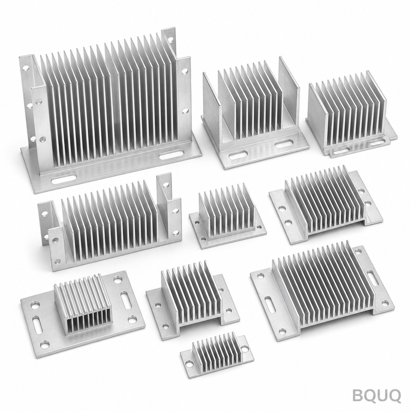
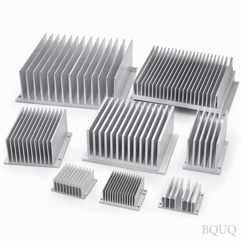
A solid heat sink is a monolithic block or a base with attached fins, produced by CNC machining, die casting, or extrusion. Tolerances are straightforward: ±0.1mm on fin spacing and ±0.05mm on base flatness. No internal cavities exist, so there is zero risk of leakage or wick failure.
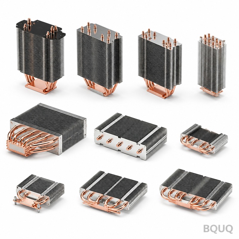
A heat pipe is a sealed copper tube with an internal wick structure (sintered powder, groove, or mesh) containing a small amount of water. The manufacturing process involves tube drawing, wick insertion, end crimping, vacuum evacuation, and water charging. Critical tolerances include outer diameter ±0.05mm, length ±1mm, and a leak rate below 1×10⁻⁸ atm·cc/s. The effective length ranges from 30mm to 300mm, with a minimum bend radius of 3x the pipe diameter.
A vapor chamber is essentially a flat heat pipe, constructed from two copper plates (top and bottom) bonded by brazing or diffusion welding. The internal cavity is 0.5-1.5mm high, with sintered copper powder wicks on both internal surfaces and support pillars (arrays of copper posts) to prevent collapse under atmospheric pressure. Manufacturing tolerances are tighter: overall thickness ±0.1mm, flatness 0.05mm across 100mm, and surface roughness Ra 0.8μm for optimal TIM (thermal interface material) contact.
Cost and Lead Time Comparison
Pricing varies significantly with volume and complexity. For a mid-sized heat sink (100mm x 100mm x 25mm), aluminum CNC machining costs $3-8 per unit at 1,000 pieces. A copper heat pipe costs $1.5-3.0 each at volume, but requires a separate base block and assembly labor. A vapor chamber costs $8-15 per unit at 1,000 pieces, including the base plate but excluding fins.
| Solution | Unit Cost (1k pcs) | Tooling Cost | Lead Time | Weight (100x100mm) | Max Operating Temp |
| Solid Aluminum (extruded) | $2.50 - $4.00 | $800 - $1,500 | 2 - 3 weeks | 350g | 200°C |
| Solid Copper (CNC) | $6.00 - $12.00 | $500 - $1,000 | 1 - 2 weeks | 890g | 200°C |
| Heat Pipe Assembly | $5.00 - $9.00 | $1,000 - $2,000 | 3 - 4 weeks | 420g | 100°C (water) |
| Vapor Chamber + Fins | $12.00 - $20.00 | $2,500 - $5,000 | 4 - 6 weeks | 480g | 100°C (water) |
The cost per watt of dissipated heat is revealing. For a 50W application, solid aluminum costs $0.08/W, heat pipe costs $0.14/W, and vapor chamber costs $0.30/W. For a 300W application, vapor chamber becomes cost-competitive at $0.05/W versus $0.04/W for heat pipe assembly, but the vapor chamber offers a 40% thinner profile.
Application Selection Criteria
Choose a solid heat sink when power density is below 10W/cm² and the heat source area is smaller than 20mm x 20mm. Typical applications include LED bulbs (5-15W), power resistors, and low-end CPU coolers. The advantages are simplicity, zero maintenance, and unlimited orientation freedom.
Choose heat pipes when you need to move heat from a compact source to a distant fin stack. Examples include laptop cooling (heat pipes route heat from CPU to edge fins), high-performance graphics cards, and industrial inverters. Heat pipes excel in constrained spaces where the heat source and sink are separated by 50-200mm. However, performance degrades by 5-10% when the condenser is above the evaporator (against gravity).
Choose a vapor chamber when the heat source is large (over 25mm x 25mm) and the heat flux exceeds 50W/cm². High-end GPU cards, server CPUs, and laser diode arrays benefit from vapor chamber's planar spreading. The key advantage is eliminating the "hot spot" directly above the die. A vapor chamber reduces peak temperature by 8-15°C compared to a solid copper base of equal thickness.
Thermal Resistance and Interface Considerations
The total thermal resistance path includes the junction-to-case, case-to-spreader, spreader-to-fin, and fin-to-ambient. A solid heat sink has no internal interface, so the bottleneck is the TIM layer. With a 50μm TIM layer of 5 W/m·K, the interface resistance is approximately 0.25°C·cm²/W. A vapor chamber adds an internal resistance of 0.05-0.1°C/W but improves the spreading resistance significantly.
Spreading resistance is calculated as: R_spread = (1/(2·k·√A))·(1 - (A_source/A_base)^0.5), where k is conductivity and A is area. For a 10mm x 10mm die on a 100mm x 100mm base, the spreading resistance for aluminum is 0.8°C/W, for copper 0.35°C/W, and for a vapor chamber effectively 0.05°C/W due to the two-phase internal convection.
Reliability and Failure Modes
Solid heat sinks have virtually infinite life if corrosion is managed. Aluminum requires anodizing (MIL-A-8625, Type II, 18μm thickness) to prevent galvanic corrosion with copper fasteners. Copper requires nickel or tin plating.
Heat pipes fail by working fluid depletion. At 60°C operating temperature, water vapor permeates through the copper wall at a rate of 1×10⁻¹⁰ g/cm²·s, giving a service life of 5-8 years at 90°C. Vapor chambers have a larger surface area, increasing permeation risk, so they are typically rated for 50,000 hours (5.7 years) continuous operation at 80°C. Both require vacuum integrity; any leak degrades performance immediately.
For high-reliability applications (aerospace, automotive), choose heat pipes with copper-water construction and a minimum wall thickness of 0.3mm. Vapor chambers should have a burst pressure rating above 20 atmospheres to survive solder reflow processes.
Practical Engineering Recommendations
For your next thermal design, follow this decision matrix. If the total power is under 30W and the heat source is small, use an extruded aluminum heat sink with a copper insert. If the power is 30-150W and space is constrained, use 2-4 heat pipes of 6mm diameter with a copper base. If the power exceeds 150W or the heat source area exceeds 400mm², specify a vapor chamber with a thickness of 2.5-3.0mm.
Always request a thermal simulation (CFD) before prototyping. At BQUQ, we use FloTHERM and Icepak to predict junction temperatures within ±3°C of measured results. Verify the TIM application: a 25μm bond line thickness reduces thermal resistance by 40% compared to a 75μm layer. For vapor chambers, specify the flatness requirement as 0.05mm to ensure proper contact with the CPU die.
For production, consider the total cost of ownership. A vapor chamber with a 3°C lower temperature allows a 10% increase in clock speed or a 15% reduction in fan speed, leading to lower acoustic noise and higher product reliability. The payback period for the higher cost is typically under 18 months for server-class products.
Conclusion and Contact
The choice between vapor chamber, heat pipe, and solid heat sink depends on power density, spatial constraints, and thermal budget. Solid heat sinks serve below 50W, heat pipes excel at remote transport over 50-200mm distances, and vapor chambers dominate for large flat sources above 150W. Always prototype and test under real operating conditions, as manufacturer datasheets can overstate performance by 20-30%.
At BQUQ, we have manufactured over 2 million thermal components since 2004, including precision CNC heat sinks, copper vapor chambers, and sintered heat pipes for clients in automotive, telecom, and consumer electronics. Our engineering team provides free thermal consultation and DFM feedback within 12 hours of receiving your CAD files. For a detailed quote on your specific application, email your drawings to sc@bquq.com, or contact us on WhatsApp at +86 13713157787. Visit www.bquq.com to view our case studies and manufacturing capabilities.
Related Articles
- How to Attach a Heat Sink Without Screws: Thermal Adhesive Guide
- Stamped Metal vs Die Cast Heat Sinks: Cost & Quality Comparison
- Hardware heat sink reconstruction under liquid-cooled penetration of AI server: cold plate, microchannel and two-phase flow
Frequently Asked Questions
What is the main difference between a vapor chamber, heat pipe, and solid heat sink?
The key difference is their heat spreading mechanism and effective thermal conductivity. A solid heat sink relies on conduction through metal (200-400 W/m·K), a heat pipe transfers heat in one direction via phase change (up to 50,000 W/m·K), and a vapor chamber spreads heat in two dimensions across a planar surface (up to 20,000 W/m·K).
Which cooling solution is best for a 100W CPU cooler?
For a 100W CPU cooler, a vapor chamber base with optimized fins achieves the lowest thermal resistance at 0.15°C/W, compared to 0.3°C/W for a heat pipe assembly and 0.8°C/W for a solid copper base with aluminum fins. This results in a temperature difference of only 7.5°C at 50W dissipation.
What are the manufacturing tolerances for a solid heat sink?
Solid heat sinks are produced by CNC machining, die casting, or extrusion with straightforward tolerances: ±0.1mm on fin spacing and ±0.05mm on base flatness. They have no internal cavities, so there is zero risk of leakage or wick failure.
What is the maximum heat flux and thickness range for a vapor chamber?
A copper vapor chamber can handle a maximum heat flux of 100-300 W/cm², with a thickness range of 1.5-5.0mm. Its thermal resistance is 0.05-0.3°C/W, and it operates in a temperature range of 0 to 100°C when using water as the working fluid.


