
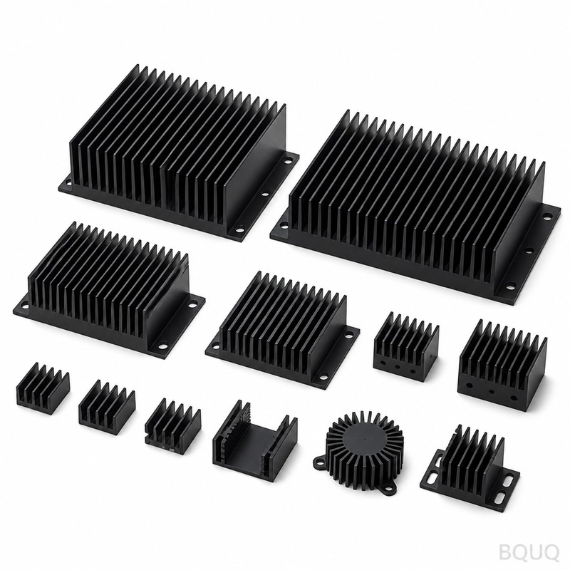
What Are the Best Heat Sink Solutions for 5G Telecom Equipment?
The best heat sink solutions for 5G and telecom equipment are high-density, forced-convection aluminum fin stacks or copper vapor chambers, depending on the power envelope and form factor. For base stations operating above 150 W, aluminum bonded-fin or skived-fin heat sinks with a thermal resistance below 0.08 °C/W are standard, while for compact remote radio units (RRUs) under 100 W, vapor chambers with a thermal conductivity of 3000 W/m·K outperform solid copper. At BQUQ, we manufacture these precision thermal components with tolerances of ±0.02 mm on fin pitch, ensuring reliable dissipation of 10–500 W heat loads in outdoor and indoor telecom environments.
What Are the Primary Heat Sources in 5G Telecom Equipment?
The primary heat sources in 5G equipment are the power amplifiers (PAs), baseband processing units, and field-programmable gate arrays (FPGAs). A typical 64-transmit/64-receive (64T64R) massive MIMO antenna array can dissipate between 200 W and 400 W of heat, with individual gallium nitride (GaN) PAs generating 20–50 W each. These components have maximum junction temperatures of 105 °C to 125 °C, requiring a heat sink to maintain a case-to-ambient temperature difference of no more than 40 °C under peak load. Additionally, the power supply units (PSUs) contribute 30–60 W per unit, and the optical transceivers add another 5–10 W each, all of which must be managed within a sealed or semi-sealed enclosure to prevent moisture ingress.
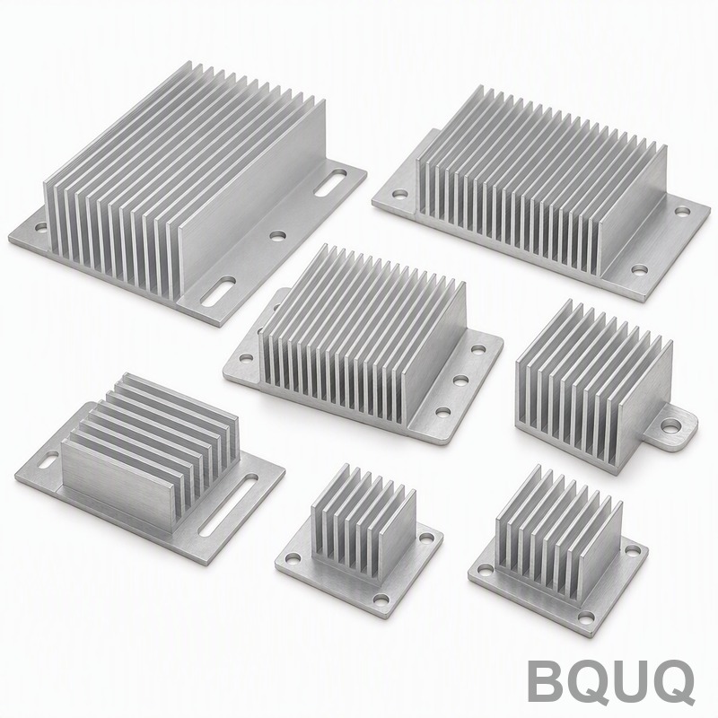
How Does High-Density Fin Geometry Improve Thermal Performance in 5G Heat Sinks?
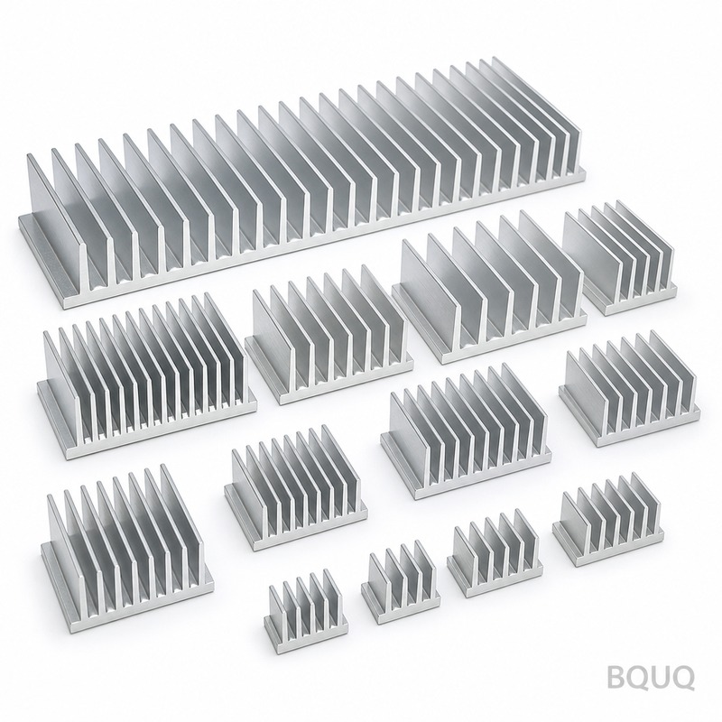
High-density fin geometry improves thermal performance by increasing the surface area available for convective heat transfer without expanding the heat sink footprint. For a standard aluminum heat sink with a base of 200 mm by 200 mm, increasing the fin density from 8 fins per inch (FPI) to 16 FPI raises the total surface area from approximately 0.32 m² to 0.58 m², a gain of 81%. This directly reduces thermal resistance; for example, a 16 FPI design with 2.0 mm fin thickness and 1.5 mm gaps can achieve a thermal resistance of 0.05 °C/W at an airflow of 3 m/s, compared to 0.09 °C/W for a 8 FPI design at the same flow rate. However, the pressure drop across the heat sink also increases from 50 Pa to 180 Pa, so engineers must balance fin density against the available fan static pressure, which is typically 200–400 Pa in telecom enclosures.
Which Materials Are Optimal for 5G Telecom Heat Sink Fabrication?
The optimal materials for 5G telecom heat sinks are aluminum alloys 6063-T5 and 6061-T6 for extruded and skived designs, and C1100 or C1020 copper for vapor chambers and high-heat-flux inserts. Aluminum 6063-T5 offers a thermal conductivity of 209 W/m·K and a yield strength of 145 MPa, making it ideal for extruded profiles up to 300 mm in length with fin ratios of 1:10. For higher performance, C1020 copper provides 391 W/m·K thermal conductivity and is used in vapor chambers that can spread heat from a 20 mm by 20 mm die area to a 120 mm by 120 mm base with a thermal resistance of just 0.02 °C/W. In hybrid designs, we use a copper base plate (3 mm thick) bonded to aluminum fins via brazing, which achieves a bond-line thermal resistance of 0.01 °C/W, offering a cost-performance trade-off where copper is 3.5 times more expensive than aluminum per kilogram but delivers a 25–30% thermal improvement.
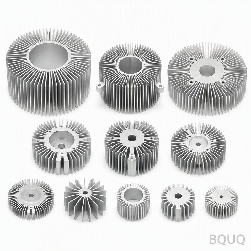
How Does Forced Convection vs. Natural Convection Affect 5G Heat Sink Sizing?
Forced convection is mandatory for 5G heat sinks with power densities above 0.5 W/cm², while natural convection is only viable for low-power remote units below 30 W. In a natural convection scenario, a 150 W heat sink would require a fin area of 1.2 m² and a volume of 6 liters, making it impractical for pole-mounted installations where the maximum envelope is 400 mm by 300 mm by 80 mm. With forced convection using a 40 mm axial fan delivering 30 CFM, the same 150 W heat load can be managed with a fin area of 0.35 m² and a volume of 1.8 liters, a reduction of 70%. For outdoor 5G base stations, the airflow is typically 2–5 m/s across the fin array, and the heat sink must be designed to maintain a noise level below 55 dBA for urban deployments, which limits fan speed to 2500–3500 RPM and dictates a minimum fin gap of 1.5 mm to avoid audible turbulence.
What Are the Standard Manufacturing Tolerances for Telecom Heat Sinks?
Standard manufacturing tolerances for telecom heat sinks at BQUQ are ±0.05 mm for base flatness, ±0.02 mm for fin pitch, and ±0.1 mm for overall height, ensuring consistent thermal contact with the component. The base surface must achieve a flatness of 0.05 mm over 150 mm length to guarantee a thermal interface material (TIM) bond line of 0.05 mm or less, which keeps the contact resistance below 0.02 °C·cm²/W. For skived heat sinks, we hold fin thickness tolerance at ±0.03 mm and fin height at ±0.10 mm, with a surface roughness of Ra 0.8 µm on the base and Ra 1.6 µm on the fins. These tolerances are critical because a 0.1 mm deviation in fin height can reduce airflow efficiency by 5% and increase thermal resistance by 7%, directly impacting the junction temperature of the GaN amplifiers.
How Does the Heat Sink Surface Finishing Impact 5G Telecom Performance?
Surface finishing impacts 5G telecom performance by enhancing emissivity for radiation heat transfer and protecting against corrosion in outdoor environments. A black anodized coating (per MIL-A-8625, Type II, 18–25 µm thickness) increases the surface emissivity from 0.04 (bare aluminum) to 0.85, which improves radiation heat dissipation by up to 15% in natural convection or low-flow scenarios. For outdoor 5G units exposed to salt spray and humidity, a chromate conversion coating plus a powder coat of 60–80 µm thickness provides 500 hours of salt spray resistance per ASTM B117, preventing fin degradation that would otherwise increase thermal resistance by 20% over five years. However, we recommend against nickel plating on the base contact area because it adds 0.02 °C/W of thermal resistance; instead, we mask the base and apply only anodizing or leave it bare for direct TIM contact.
What Is the Cost and Lead Time for Prototype and Production 5G Heat Sinks?
The cost and lead time for 5G heat sinks vary significantly between prototype and production phases, with tooling being the dominant upfront expense. For an extruded aluminum heat sink with a custom profile, the extrusion die cost is $800–$1,500 and takes 2–3 weeks to fabricate, with sample parts delivered in 3–4 weeks. Skived heat sinks require no tooling for the fins but need custom CNC fixtures at $500–$1,000, with prototypes available in 1–2 weeks. For production, a typical 5G base station heat sink (200 mm by 200 mm by 60 mm, 16 FPI) costs $18–$35 per unit for quantities of 1,000 pieces, dropping to $12–$20 per unit at 10,000 pieces due to reduced machining time. Vapor chambers add a premium of $8–$15 per unit for the chamber itself plus $5–$8 for the copper base, bringing the total to $40–$60 per unit at 5,000 quantity with a lead time of 4–6 weeks.
| Heat Sink Type | Thermal Resistance (°C/W) | Max Power (W) | Unit Cost at 1,000 pcs (USD) | Lead Time (Weeks) | Fin Density (FPI) |
| Extruded Aluminum (6063-T5) | 0.08–0.12 | 150 | $18–$25 | 3–4 | 8–12 |
| Skived Aluminum (6061-T6) | 0.05–0.08 | 250 | $25–$35 | 2–3 | 14–20 |
| Bonded Fin (Al base + Cu fins) | 0.04–0.06 | 350 | $35–$45 | 4–5 | 16–24 |
| Vapor Chamber (Copper C1020) | 0.02–0.04 | 500 | $40–$60 | 4–6 | 20–30 |
| Die-Cast Aluminum (A380) | 0.10–0.15 | 100 | $12–$18 | 5–6 | 6–10 |
When Should You Choose a Vapor Chamber Over a Traditional Fin Stack?
You should choose a vapor chamber over a traditional fin stack when the heat source is highly concentrated (heat flux above 50 W/cm²) and the available space for the heat sink base is less than 50 mm in one dimension. For example, a single GaN PA die measuring 5 mm by 5 mm dissipating 25 W creates a heat flux of 100 W/cm², which would cause a local hot spot of 15 °C above the base temperature in a solid aluminum base. A vapor chamber spreads this heat across a 100 mm by 100 mm area in 0.5 seconds, reducing the hot spot to 3 °C and allowing the fins to work uniformly. Additionally, vapor chambers are the only viable option for sealed IP65 enclosures where airflow is limited to the external fins, as they can transfer heat through the enclosure wall with a thermal resistance of 0.03 °C/W.
How Do I Calculate the Required Heat Sink Size for My 5G Module?
Calculate the required heat sink size by determining the total power dissipation (P) and the maximum allowable case temperature (T_case), then divide by the ambient temperature (T_amb) and the desired thermal resistance (R_th = (T_case - T_amb) / P). For a 200 W module with a maximum case temperature of 85 °C and an ambient of 45 °C, the required thermal resistance is (85-45)/200 = 0.20 °C/W. Using a forced convection heat sink with 0.05 °C/W per 100 mm of fin length, you would need 400 mm of total fin length, which can be achieved with a 200 mm by 200 mm footprint and 16 FPI.
What Is the Maximum Ambient Temperature for Outdoor 5G Heat Sinks?
The maximum ambient temperature for outdoor 5G heat sinks is typically 55 °C, based on IEC 60068-2-2 standards for solar-loaded equipment in tropical climates. At this ambient, the heat sink must maintain the component junction temperature below 105 °C, leaving a 50 °C temperature differential for the entire thermal path. In practice, we design for a worst-case ambient of 60 °C with a derating factor of 10% on thermal performance to account for dust accumulation on the fins.
Can I Use the Same Heat Sink Design for Both Indoor and Outdoor 5G Equipment?
No, you cannot use the same heat sink design for both indoor and outdoor 5G equipment because the environmental requirements differ significantly. Outdoor units require IP65-rated sealing, corrosion-resistant coatings (at least 500 hours salt spray), and a fin gap of at least 2 mm to prevent debris clogging, while indoor units can use tighter fins (1.5 mm gap) and lighter anodizing. Additionally, outdoor heat sinks need a steeper fin angle (5–7 degrees) to shed water, whereas indoor designs can use vertical fins for maximum airflow.
How Does Altitude Affect Heat Sink Performance in 5G Telecom Deployments?
Altitude reduces air density, which decreases convective heat transfer coefficient by approximately 3% per 1000 meters of elevation gain. At 3000 meters altitude, a heat sink designed for sea level will have 9% higher thermal resistance, meaning the component junction temperature will rise by 9 °C for a 100 W load. To compensate, we recommend derating the power by 10–15% or increasing the fan speed by 20% when deploying above 2000 meters.
What Are the Common Failure Modes of 5G Heat Sinks?
The common failure modes of 5G heat sinks are fin clogging from dust and insects, corrosion of the fin edges, and fatigue cracking at the base-to-fin joints due to thermal cycling. Thermal cycling between -40 °C and +85 °C can cause differential expansion between aluminum and copper, leading to solder joint fatigue after 10,000 cycles. To mitigate this, we use a compliant TIM layer and a mechanical clamping force of 50–100 N to maintain contact pressure of 10–20 psi.
How Can I Validate the Thermal Performance of a Custom Heat Sink?
Validate the thermal performance by conducting a CFD simulation followed by a physical test using thermocouples and a heat source that mimics the actual power dissipation. In the physical test, mount thermocouples at the heat sink base and the component case, apply the rated power, and measure the steady-state temperature after 30 minutes. The measured thermal resistance should be within 5% of the simulated value; if it is higher, check the TIM bond line and base flatness.
What Is the Minimum Order Quantity for Custom 5G Heat Sinks?
The minimum order quantity for custom 5G heat sinks is 500 pieces for extruded designs and 300 pieces for skived designs, due to the setup costs for CNC machining and surface finishing. For prototype validation, we offer a low-volume service with a minimum of 20 pieces at a 30% cost premium per unit. For vapor chamber designs, the MOQ is 1,000 pieces because of the custom tooling required for the chamber sealing process.
For high-density 5G thermal solutions, the key is matching the heat sink architecture to your specific power envelope, airflow, and environmental constraints. Whether you need a 16 FPI skived aluminum fin stack for a 250 W remote radio unit or a copper vapor chamber for a 500 W massive MIMO array, our 20 years of CNC machining and thermal fabrication experience ensures precise tolerances and reliable performance. Contact BQUQ for a 12-hour quoting response and free thermal design review. Email us at sc@bquq.com, reach us on WhatsApp at +86 13713157787, or visit www.bquq.com to discuss your project.


