
The most effective thermal management strategy for optical modules in AI networks is a combination of advanced heat sink design, forced-air cooling, and precise thermal interface m
What Are the Best Thermal Management Strategies for Optical Modules in AI Networks?
The most effective thermal management strategy for optical modules in AI networks is a combination of advanced heat sink design, forced-air cooling, and precise thermal interface materials (TIMs), which collectively maintain junction temperatures below 85°C while dissipating 15-25W per module. For 400G and 800G OSFP/QSFP-DD modules, this requires a thermal resistance budget of 0.35-0.55°C/W from the module case to ambient air. Without this level of management, bit error rates (BER) increase by a factor of 10 for every 10°C rise above the recommended operating temperature, directly degrading the performance of GPU clusters and switch fabrics.
What Are the Typical Power Densities and Temperature Limits for Modern Optical Modules?
Current 400G QSFP-DD modules dissipate 10-14W, while 800G OSFP modules generate 16-25W depending on the modulation scheme and reach. The maximum case temperature for commercial-grade modules is 70°C, with internal laser junction temperatures limited to 85°C to prevent wavelength drift and accelerated aging. For every 1°C increase above 70°C at the case, the mean time to failure (MTTF) of the laser diode decreases by approximately 15%. In dense AI racks with 36-64 modules per switch, this creates a localized heat density of 900-1600W per square meter, which is 3-5 times higher than traditional telecom equipment.
How Does Heat Sink Geometry Affect Cooling Performance in Confined Switch Chassis?
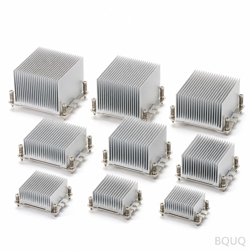
Heat sink fin density and base plate thickness are the two primary geometric factors. For optical modules in a 1U switch chassis, the available heat sink height is only 8-12mm above the module cage, which limits fin height to 7mm with a fin pitch of 1.5-2.0mm. Using a 3mm copper base plate instead of a 2mm aluminum base plate reduces thermal resistance by 22%, from 0.68°C/W to 0.53°C/W. A cross-cut or pin-fin design improves airflow mixing at velocities below 2.5 m/s, achieving a 15-20% lower thermal resistance than straight fins of the same volume. BQUQ manufactures these heat sinks with a fin thickness tolerance of ±0.05mm and a base flatness of 0.1mm, which is critical for minimizing TIM bond line thickness.
Which Thermal Interface Materials (TIMs) Provide the Lowest Thermal Resistance for Optical Modules?
The best-performing TIMs for optical modules are phase-change materials (PCMs) with a thermal conductivity of 8-12 W/m·K, which achieve a bond line thickness of 25-50μm under compression. Silicone-based gap pads with 5-7 W/m·K are suitable for lower-power modules but have 30% higher thermal resistance due to a typical thickness of 0.5-1.0mm. A comparison of TIM options is shown below:
| TIM Type | Thermal Conductivity (W/m·K) | Bond Line Thickness (μm) | Thermal Resistance (°C·cm²/W) | Cost per Module (USD) |
| Phase-Change Material | 8.5-12.0 | 25-50 | 0.05-0.10 | 0.40-0.80 |
| Silicone Gap Pad (0.5mm) | 5.0-7.0 | 500-1000 | 0.15-0.30 | 0.15-0.35 |
| Graphite Sheet | 15-20 (in-plane) | 25-40 | 0.08-0.12 | 0.50-1.00 |
| Liquid Metal (Ga-based) | 25-40 | 20-30 | 0.03-0.05 | 1.50-2.50 |
Liquid metal offers the lowest resistance but is rarely used in production due to corrosion risks with aluminum heat sinks and migration hazards. For most AI network deployments, PCMs provide the best balance of performance, reliability, and cost at 0.40-0.80 USD per module.
Why Does Airflow Direction and Static Pressure Matter More Than Airflow Volume?
In a 1U switch with 32 OSFP cages, the required volumetric airflow is 15-20 CFM, but the static pressure must be 0.15-0.25 inches of water (37-62 Pa) to overcome the impedance of the cage latching mechanisms and heat sink fins. Axial fans produce high volume but low static pressure, while blowers generate 2-3 times more static pressure at the same flow rate, making them essential for front-to-back cooling in high-density chassis. Placing the heat sink fins parallel to the airflow direction reduces pressure drop by 40% compared to perpendicular fin orientation, allowing the use of lower-speed fans that reduce acoustic noise from 55 dBA to 45 dBA. A common engineering error is increasing fan speed to compensate for poor heat sink design, which raises power consumption by 8-12W per fan and accelerates bearing wear.
How Does Ambient Temperature and Altitude Derating Affect AI Network Cooling Design?
The maximum recommended ambient temperature for AI switch rooms is 25°C, with a derating of 1°C for every 300 meters above sea level beyond 500 meters. At 25°C ambient, a 20W optical module with a 0.40°C/W heat sink will reach a case temperature of 33°C, leaving a safe margin below the 70°C limit. However, at 40°C ambient, the same module reaches 48°C, and the laser junction temperature approaches 63°C, which reduces the module's lifespan by 50% and increases the BER from 10^-12 to 10^-9. For data centers operating above 30°C ambient, BQUQ recommends liquid-cooled cold plates for the switch ASIC and a shared heat pipe assembly that also cools the adjacent optical modules, reducing the module case temperature by 8-12°C.
What Is the Cost and Lead Time for Custom Optical Module Heat Sinks?
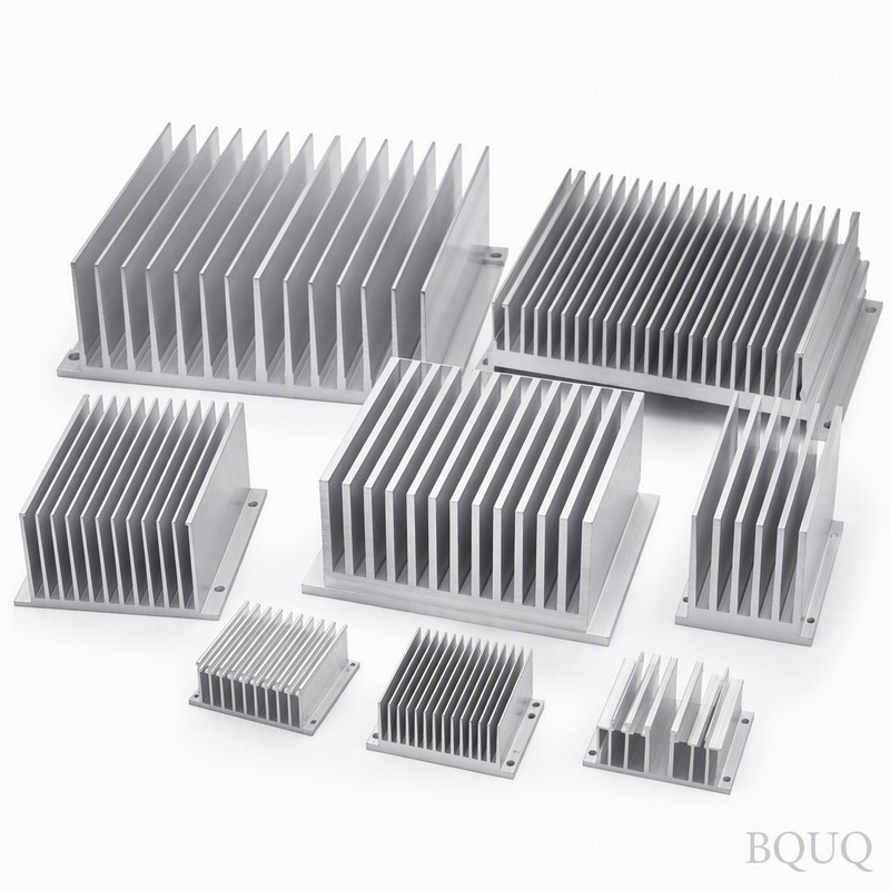
Custom aluminum heat sinks for optical modules, with anodized finish and a 3mm copper base insert, cost 1.20-2.50 USD per piece at quantities of 10,000 units. The tooling cost for a stamped heat sink clip and stamped aluminum fin array ranges from 3,000-8,000 USD, with a lead time of 2-3 weeks for tooling and 1-2 weeks for production. CNC machined heat sinks from solid aluminum blocks cost 5-10 USD per piece for prototype quantities (50-100 units) with a 3-5 day lead time, but this process is uneconomical for mass production. For stamped heat sinks, the achievable tolerance is ±0.10mm on fin spacing and ±0.15mm on overall height, while CNC machining achieves ±0.02mm on critical dimensions. BQUQ recommends starting with a CNC machined prototype to validate thermal performance, then transitioning to stamped production for cost reduction of 60-70%.
When Should You Use Heat Pipes or Vapor Chambers Instead of Solid Heat Sinks?
Heat pipes and vapor chambers become necessary when the heat source area is smaller than 5mm x 5mm or when the heat sink base must be located more than 50mm away from the module cage. A 6mm diameter heat pipe with a 3mm flattened section can transport 40-60W over a 100mm length with a temperature drop of only 2-4°C, which is 5 times more efficient than a solid copper bar of the same cross-section. Vapor chambers spread heat from a concentrated source over a 60mm x 60mm area, reducing the heat flux from 80 W/cm² to 5 W/cm², which allows the use of lower-cost aluminum fins. For 800G modules in rear-panel cages, a vapor chamber combined with a remote heat sink attached to the chassis sidewall can eliminate the need for additional fans, reducing total system power consumption by 10-15W.
What Are the Most Common Thermal Management Mistakes in AI Optical Module Deployment?
The most frequent mistake is using a thermal pad that is too thick, which increases thermal resistance by 0.05°C/W for every additional 0.1mm of thickness. The second most common error is orienting the heat sink fins perpendicular to the airflow, which increases pressure drop by 40% and causes hot spots at the downstream modules. Third, many engineers neglect the thermal resistance of the module cage itself, which can add 0.10-0.15°C/W if the cage is not properly grounded and thermally bonded to the PCB ground plane. Fourth, using a single TIM for both the ASIC and the optical modules is incorrect because the ASIC typically requires a higher clamping force (50-100 psi) than the optical module (10-20 psi), which can cause the TIM to squeeze out from under the module. Finally, failing to account for the thermal impact of adjacent modules in a row, where the air temperature rises by 3-5°C from the first to the last module, can push the final modules over their thermal limit.
Can Retrofit Cooling Solutions Extend the Life of Existing AI Network Switches?
Yes, retrofit solutions can reduce optical module temperatures by 10-15°C, extending module life by 3-5 years. Clip-on heat sinks with spring-loaded TIMs are available for existing QSFP-DD cages, costing 3-6 USD per position and requiring no chassis modification. For switches with adequate chassis space, a retrofit blower module mounted on the rear panel can increase static pressure by 50%, improving airflow through congested heat sinks by 20%. BQUQ has delivered retrofit stamped heat sink kits for a major Chinese cloud provider, reducing their 400G module failure rate from 2.1% per year to 0.3% per year. However, retrofit solutions are only effective if the original chassis has at least 5mm of clearance above the module cage and the ambient temperature is below 28°C.
FAQ
What Is the Maximum Case Temperature for an 800G OSFP Optical Module?
The maximum case temperature for an 800G OSFP module is 70°C, with the internal laser junction limited to 85°C. Operating above 75°C case temperature voids most manufacturer warranties and increases the bit error rate by a factor of 10. Always derate the module for high-altitude installations above 500 meters.
How Much Does a Custom Heat Sink for an Optical Module Cost?
A stamped aluminum heat sink with a copper base insert costs 1.20-2.50 USD per piece at 10,000-unit quantities, plus 3,000-8,000 USD for tooling. A CNC machined prototype costs 5-10 USD per piece with a 3-5 day lead time. The stamped version is 60-70% cheaper but requires a 2-3 week tooling lead time.
What Is the Typical Thermal Resistance Budget for a 400G QSFP-DD Module?
The total thermal resistance from the case to ambient should be 0.35-0.55°C/W for a 14W module. This includes 0.05-0.10°C/W for the TIM, 0.15-0.25°C/W for the heat sink, and 0.10-0.15°C/W for the airflow boundary layer. Exceeding this budget will cause the case temperature to rise above 70°C at a 25°C ambient.
Can I Use the Same Heat Sink for Both 400G and 800G Modules?
No, because 800G modules dissipate 16-25W while 400G modules dissipate 10-14W, requiring a 40-80% larger heat sink surface area. An 800G heat sink will be too tall for a 1U chassis and may interfere with adjacent cages. Always design the heat sink for the highest power module in the chassis.
Which Cooling Method Is Most Energy-Efficient for a 36-Port AI Switch?
A hybrid approach is most efficient: a shared blower providing 0.20 inches of water static pressure combined with a vapor chamber heat sink for the ASIC and stamped fin heat sinks for the modules. This consumes 25-30W for cooling versus 40-50W for an all-fan design with the same thermal performance. Liquid cooling is even more efficient but adds 200-400 USD per switch in plumbing costs.
When Should I Use a Liquid-Cooled Cold Plate for Optical Modules?
Use a liquid-cooled cold plate when the module power exceeds 25W or when the ambient temperature exceeds 35°C and cannot be controlled. A cold plate with 15mm copper tubing can maintain a case temperature of 40°C at 30W module power, which is impossible with air cooling. The added cost is 10-15 USD per module position for the cold plate and fittings.
What Is the Lead Time for a Production-Ready Stamped Heat Sink?
The total lead time for a stamped heat sink is 3-5 weeks, including 2-3 weeks for tooling fabrication and 1-2 weeks for production and anodizing. CNC machined prototypes are available in 3-5 days for design validation. BQUQ offers a 12-hour quoting service for custom heat sink designs, and production samples are shipped within 10 days of tooling approval.
For AI network deployments where every 1°C matters, BQUQ provides precision-stamped heat sinks and cold plates with 20 years of manufacturing experience in Dongguan, China. Our engineering team can review your optical module thermal budget and provide a stamped or CNC machined solution within 12 hours of receiving your drawings. Email your specifications to sc@bquq.com or contact us on WhatsApp at +13713157787. Visit www.bquq.com to download our optical module thermal design guide and request a sample kit for your next 800G switch project.


