
What Are the Best Thermal Solutions for EV Charger Cooling?
The best thermal solutions for EV fast-charging infrastructure combine liquid cooling for high-power cables and connectors, forced-air cooling for power electronics, and phase-change materials for thermal buffering, with liquid cooling being mandatory for systems above 250 kW. For a 350 kW charger, a liquid-cooled cable assembly maintains a surface temperature below 60°C while carrying 600 A, whereas an air-cooled equivalent would require a cable diameter of 120 mm and exceed safe touch limits. Below, we detail the engineering specs, cost data, and design rules you need to specify a reliable thermal management system for DC fast chargers (DCFC).
How Much Heat Does an EV Fast Charger Generate per Charge Session?
A 350 kW DCFC with 94% system efficiency dissipates approximately 21 kW of heat during a 20-minute charge session, totaling 7 kWh of thermal energy per vehicle. Power conversion stages (AC-DC rectifier and DC-DC converter) account for 65% of this loss, while cables and connectors contribute 25%, and auxiliary systems (control boards, contactors) account for the remaining 10%. At 500 V and 700 A, a single liquid-cooled connector pair generates about 300 W of heat at the contact interface, requiring a coolant flow rate of 2.5 L/min to keep the contact temperature below 90°C.
What Are the Four Main Cooling Architectures for DCFC Systems?
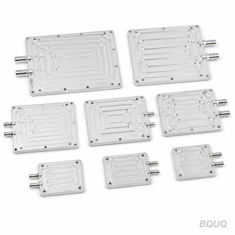
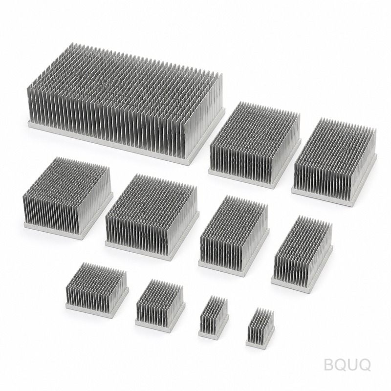
The four primary architectures are passive air cooling, forced-air cooling, liquid cooling (cold plate and hose), and immersion cooling. Passive air cooling (natural convection) is limited to chargers below 50 kW, where heat density stays under 0.05 W/cm². Forced-air cooling handles 50–150 kW with finned heatsinks and axial fans moving 300–800 CFM, achieving thermal resistance of 0.05–0.15 °C/W. Liquid cooling via cold plates is standard for 150–350 kW, with thermal resistance of 0.01–0.03 °C/W and coolant temperatures of 30–45°C. Immersion cooling, using dielectric fluids like synthetic esters, is emerging for 500 kW+ systems but adds 15–20% cost and requires sealed enclosures.
Which Components in a Charger Require Active Cooling and Why?
The three critical components are IGBT/SiC power modules, charging cables, and connector assemblies. IGBT modules dissipate up to 400 W/cm² at peak load; without active cooling, junction temperature exceeds 150°C and derating occurs above 125°C. SiC MOSFETs run cooler (junction limit 175°C) but still need cold plates because the die area is 50% smaller than IGBTs. Charging cables above 200 A require liquid cooling because resistive losses (I²R) generate 60 W/m at 600 A; a 4-meter liquid-cooled cable with 10 mm inner diameter coolant hose keeps the outer jacket under 60°C. Connector pins, typically copper alloy, need active cooling to prevent contact resistance growth; each 10°C rise above 80°C doubles oxidation rate and increases resistance by 4%.
How Do You Calculate Coolant Flow Rate and Pump Size for a 350 kW Charger?
For a 350 kW charger with 21 kW heat load, use the formula Q = m × Cp × ΔT, where Q is heat (21,000 W), Cp is coolant specific heat (3,600 J/kg·K for 50/50 water-glycol), and ΔT is the allowable temperature rise (10°C). This yields a mass flow rate of 0.58 kg/s, or approximately 35 L/min, requiring a pump with 2.5 bar head pressure to overcome 8 mm hose friction losses. For a 20-meter total hose length, pressure drop calculates to 1.8 bar; select a pump with 40 L/min at 3 bar to maintain 20% margin. A 24 V DC brushless pump with these specs consumes 180 W and costs $120–$180 in OEM volumes.
Why Is Liquid Cooling Preferred Over Air Cooling for High-Power Cables?
Liquid cooling reduces cable weight by 70% and improves ergonomics, which is critical for user acceptance. A 600 A air-cooled cable requires 120 mm² copper cross-section and weighs 8 kg per meter; a liquid-cooled equivalent uses 50 mm² copper with a 6 mm coolant tube and weighs 2.5 kg per meter. Thermal performance is superior: the convective heat transfer coefficient of flowing water-glycol (2,000–5,000 W/m²·K) is 20–50 times higher than forced air (100–250 W/m²·K). This allows a liquid-cooled cable to carry 600 A continuously with a surface temperature of 55°C, versus 95°C for an air-cooled cable at 300 A.
What Are the Real-World Costs for EV Charger Thermal Components?
Component costs for a 350 kW liquid-cooled system total $2,800–$4,200 per charger, excluding assembly labor. The table below shows typical pricing at production volumes of 500 units per year.
| Component | Specification | Unit Cost (USD) | Lead Time (weeks) |
| Cold plate (aluminum, 300×200×15 mm) | 0.02 °C/W thermal resistance | $180–$260 | 4–6 |
| Coolant pump (24 V, 40 L/min, 3 bar) | Brushless DC, IP67 | $120–$180 | 6–8 |
| Liquid-cooled cable (4 m, 600 A) | 50 mm² copper, 6 mm hose | $450–$650 | 8–10 |
| Coolant hose kit (20 m, 8 mm ID) | EPDM, -40°C to 150°C | $80–$120 | 2–3 |
| Radiator (300×300×40 mm) | Aluminum, 5 kW dissipation | $150–$220 | 4–5 |
| Fan (120 mm, 400 CFM) | Dual ball bearing, 12 V | $25–$40 | 2 |
| Coolant (50/50 premix, 10 L) | Ethylene glycol-based | $30–$50 | 1 |
| Temperature sensors (4× PT1000) | ±0.3°C accuracy | $15–$25 | 2 |
How Do Ambient Temperature and Climate Affect Cooling System Design?
Design margins must account for ambient temperature extremes, as thermal performance degrades at both high and low temperatures. For a charger rated at 350 kW, the cooling system must maintain a coolant inlet temperature below 45°C when ambient is 40°C; this requires a radiator sized for 25°C approach temperature. In cold climates (below -20°C), use a 40/60 water-glycol mix to prevent freezing, but note that viscosity increases by 300%, reducing flow by 15% and increasing pump power demand by 25%. Desert environments with high dust loads require filters on air-cooled systems; a clogged filter increases thermal resistance by 30% within 3 months, necessitating quarterly maintenance.
When Should You Consider Phase-Change Materials (PCM) for Thermal Buffering?
PCMs are beneficial for chargers with intermittent high-power sessions, such as highway rest stops, where peak demand lasts 15–20 minutes followed by idle periods. A paraffin-based PCM with a melting point of 55°C absorbs 200 kJ/kg during phase transition, buffering thermal spikes without increasing radiator size. For a 350 kW charger, installing 5 kg of PCM in the cold plate reduces peak coolant temperature by 8°C and allows a 20% smaller radiator. However, PCM adds $200–$350 cost and 3 kg weight; specify only if your charging profile has a duty cycle below 40%.
Can Retrofitting an Air-Cooled Charger to Liquid Cooling Be Done Safely?
Retrofitting is feasible for chargers with existing power module access, but only if the enclosure has space for a cold plate and coolant lines; typical retrofit cost is $1,500–$2,500 per unit. The key risk is coolant leakage onto high-voltage components, so use dielectric coolant (e.g., 3M Novec) or double-walled hoses with leak detection. Verify that the existing power modules have exposed baseplates rated for cold plate mounting; IGBT modules with insulated substrates (e.g., Al2O3) are safe, but those with direct copper bonding require additional thermal interface material. Always retest thermal performance at full load for 24 hours before deployment.
FAQ
What temperature should the coolant be for EV charger liquid cooling?
The recommended coolant inlet temperature is 30–45°C, with a maximum outlet temperature of 55°C to ensure power module junction temperatures stay below 125°C for IGBTs and 150°C for SiC. Exceeding 45°C inlet reduces thermal margin and accelerates coolant degradation, requiring earlier replacement intervals.
How often does coolant need replacement in a DCFC system?
Standard 50/50 water-glycol coolant should be replaced every 2–3 years or after 5,000 operating hours, whichever comes first. Test pH annually; if it drops below 8.0, replace immediately to prevent corrosion of aluminum cold plates.
What is the typical thermal resistance of a cold plate for a 350 kW charger?
A production cold plate achieves 0.01–0.03 °C/W thermal resistance at a flow rate of 35 L/min. This means a 400 W power module loss produces a 4–12°C temperature rise from coolant to baseplate, which is acceptable for most designs.
Which coolant is best: water-glycol or dielectric fluid?
Water-glycol (50/50) is preferred for cost and heat transfer, at $2–$3 per liter, but requires leak-proofing. Dielectric fluids like synthetic esters cost $15–$25 per liter and allow direct contact with electronics, but their heat transfer coefficient is 40% lower, requiring larger pumps and radiators.
Can a standard automotive radiator be used for EV charger cooling?
Yes, but only if derated for continuous duty; automotive radiators assume 30 mph airflow, while charger fans provide 400 CFM max. Specify a radiator with at least 30% more surface area than the calculated requirement, and use a dual-fan setup for redundancy.
What happens if the cooling pump fails during a fast-charge session?
The charger control system must derate power to 30% within 5 seconds of flow loss, and shut down completely within 60 seconds to prevent junction temperature overshoot. Install a redundant pump with automatic switchover for high-availability sites, adding $250 to cost.
How do you test a liquid-cooled charger for thermal compliance?
Perform a continuous full-power test at 40°C ambient for 2 hours, measuring coolant inlet/outlet temperature, surface temperature of cables, and power module case temperature. Pass criteria are: cable surface below 60°C, coolant outlet below 55°C, and module case below 85°C.
Conclusion
Selecting the right thermal solution for EV fast-charging infrastructure requires matching the cooling architecture to the power level, duty cycle, and ambient conditions: forced air for under 150 kW, liquid cooling for 150–350 kW, and immersion or PCM-enhanced liquid cooling for 500 kW and above. For a 350 kW charger, budget $2,800–$4,200 for thermal components and design for a 35 L/min coolant flow with a 10°C temperature rise. Always include a 20% margin on pump capacity and radiator surface area to account for aging, fouling, and extreme ambient spikes.
Need help specifying your charger cooling system? BQUQ provides free thermal design reviews with 48-hour turnaround. Contact us at sc@bquq.com or WhatsApp +86 13713157787, or visit www.bquq.com for instant quotes within 12 hours.
Related Articles
- Patent Wars: Intellectual Property Pattern and Risks of Global Hardware Heat Sink Technology
- AI simulation and intelligent manufacturing: the heat sink industry has gone from "trial and proof" to "one time right"
- From Macro Base Station to Edge Box: Transforming Heat Sink Requirements in Communication Network Evolution


