
What Are the Key Options in Extrusion Heat Sink Profile Design?
Directly answering the question: Extrusion heat sink profile design is governed by two primary paths: standard shapes that offer proven thermal performance and low tooling cost, and custom options that optimize cooling for specific geometries and power densities. Standard profiles (flat, single-fin, and dual-fin) typically achieve tolerances of ±0.1 mm and cost between USD 500 and USD 2,000 for tooling, while custom profiles can reach fin aspect ratios of 1:10 and require tooling investments of USD 3,000 to USD 15,000. The choice depends on your thermal budget, production volume, and space constraints, not merely on the heat load itself.
What Are the Standard Extrusion Heat Sink Profile Shapes?
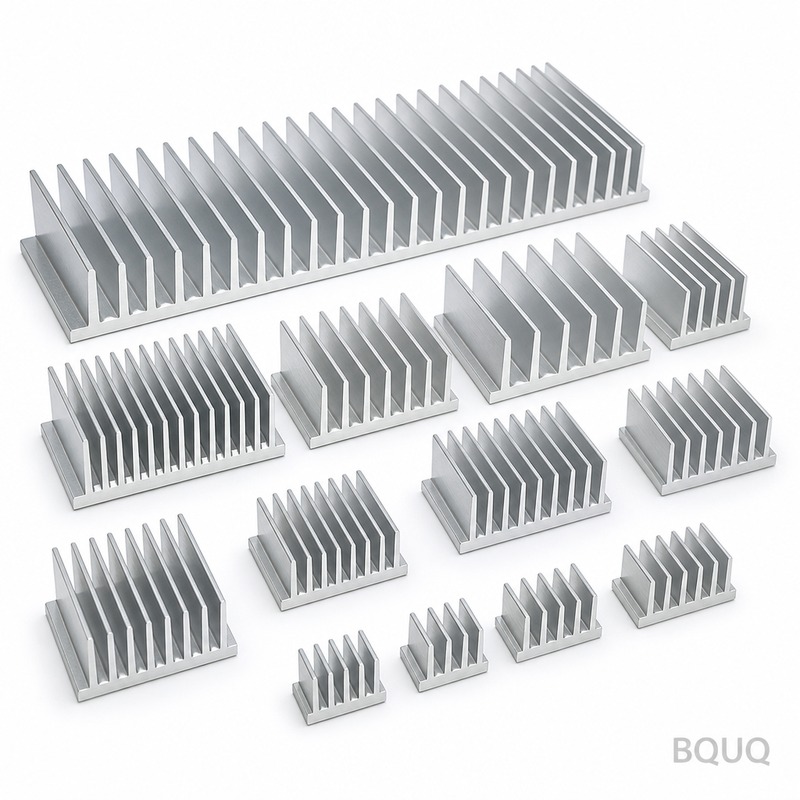
Standard extrusion profiles are defined by their fin geometry and base plate design, and they cover the majority of natural and forced convection applications. The three most common shapes are the flat plate with parallel fins, the single-side finned profile, and the dual-side finned profile. Flat plate profiles, often used for LED lighting and low-power converters, have fin heights from 5 mm to 25 mm and fin thicknesses from 1.0 mm to 2.5 mm. Single-side finned profiles are the workhorse for CPU coolers and IGBT modules, with fin heights up to 60 mm and base thicknesses of 5 mm to 10 mm. Dual-side finned profiles, used in enclosed cabinets, provide symmetrical cooling but require more complex die designs and typically add 15% to 20% to the extrusion cost per kilogram.
Standard profiles also include specific geometric ratios set by extruders. The minimum fin pitch (distance between fins) is generally 3.0 mm for 6005A-T6 aluminum, and the maximum fin height to gap ratio is 10:1. For example, a profile with 2.0 mm fins and a 3.0 mm gap can have fins up to 30 mm tall. Beyond these ratios, the aluminum flow becomes uneven, causing die deflection and inconsistent fin thickness. Standard profiles are always the first consideration because they require no engineering design fee and have lead times of 7 to 10 days for samples.
How Do Custom Extrusion Profiles Improve Thermal Performance?
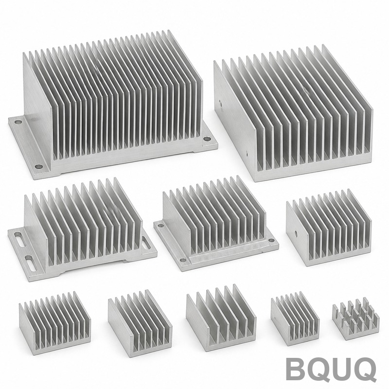
Custom profiles are engineered when standard shapes cannot meet a specific thermal resistance target or when the mounting interface is non-standard. The primary thermal advantage of a custom profile is the ability to maximize surface area within a given envelope by adjusting fin density, fin shape, and base plate thickness independently. For instance, a custom profile with tapered fins (wider at the base, narrower at the tip) can increase surface area by 8% to 12% compared to straight fins, while maintaining the same extrusion pressure. This is critical for natural convection, where the boundary layer is thick; tapered fins promote better air flow near the fin tip.
Another key improvement is the integration of mounting features, such as dovetail slots, spring clips, or embedded heat pipes, directly into the extrusion. This eliminates secondary machining operations and reduces thermal interface resistance by 30% to 50% because the heat source can be clamped directly against the solid base. Custom profiles also allow for variable fin height across the profile length, which is used to match the heat flux distribution of a component (e.g., more fins over the die hotspot, fewer fins at the edges). Thermal simulations show that such tailored designs can reduce junction-to-ambient thermal resistance (Rth j-a) by 15% to 25% compared to a standard profile of the same footprint.
What Are the Design Limits for Extrusion Heat Sink Profiles?
The extrusion process imposes strict geometric limits, and understanding these prevents costly redesigns. The maximum width of a standard aluminum extrusion is 300 mm, though some presses handle up to 400 mm with a higher per-kilogram price (typically +10%). The maximum length is 6 meters, but for heat sinks, lengths over 1.5 meters require specialized straightening to maintain a flatness tolerance of 0.5 mm per meter. Fin thickness must be at least 1.0 mm for 6063-T5 aluminum and 1.2 mm for 6061-T6; anything thinner causes die breakage during extrusion.
The most critical limit is the fin aspect ratio (height divided by gap). For a gap of 2.5 mm, the maximum fin height is 25 mm (ratio 10:1). If you exceed this, the aluminum will not fill the die cavity completely, resulting in thin or wavy fins. Also, the base plate thickness should be a minimum of 3.0 mm to avoid bowing during cooling, and the transition radius from base to fin should be 0.5 mm to 1.0 mm to reduce stress concentration. The minimum draft angle (taper) for a closed profile is 1 degree, but for open heat sink profiles, a 0.5-degree taper on the fins is sufficient to allow release from the die.
How Much Does Tooling Cost for Standard vs. Custom Profiles?
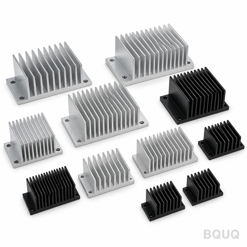
Tooling cost is the largest upfront expense in extrusion heat sink design, and it scales with die complexity and profile perimeter. A standard flat plate or single-fin profile die costs between USD 800 and USD 1,500 and has a lead time of 3 to 5 days. A custom profile die with complex features, such as hollow sections or multiple fin heights, costs between USD 3,500 and USD 8,000, with lead times of 10 to 15 days. For very large profiles (over 200 mm width) or profiles requiring a special alloy like 6061-T6, tooling can reach USD 12,000 to USD 15,000.
| Profile Type | Tooling Cost (USD) | Tooling Lead Time (Days) | Max Fin Height (mm) | Tolerance (mm) | Typical Surface Finish (Ra) |
| Standard Flat Plate | 800 - 1,200 | 3 - 5 | 25 | ±0.15 | 1.6 µm |
| Standard Single-Fin | 1,200 - 1,800 | 4 - 7 | 60 | ±0.10 | 1.6 µm |
| Standard Dual-Fin | 1,500 - 2,000 | 5 - 8 | 40 | ±0.10 | 1.6 µm |
| Custom Tapered Fin | 3,500 - 6,000 | 10 - 15 | 80 | ±0.08 | 0.8 µm |
| Custom with Hollow Sections | 6,000 - 12,000 | 15 - 20 | 50 | ±0.08 | 0.8 µm |
The tooling cost is amortized over the production volume; for volumes above 2,000 units per year, custom tooling is almost always justified because the per-unit extrusion cost is only 2% to 5% higher than standard profiles, while the thermal performance gain can eliminate the need for a larger fan or heat pipe assembly.
Which Aluminum Alloy Is Best for Extrusion Heat Sink Profiles?
The alloy choice directly impacts thermal conductivity, strength, and corrosion resistance, and the two dominant options are 6063-T5 and 6061-T6. 6063-T5 offers a thermal conductivity of 209 W/m·K and is the preferred choice for most heat sinks because it extrudes easily, allowing for thinner fins and tighter tolerances. It has a yield strength of 145 MPa, which is sufficient for most mounting applications. 6061-T6 has a slightly lower thermal conductivity of 167 W/m·K but a much higher yield strength of 276 MPa, making it suitable for profiles that serve as structural members or are subjected to vibration.
For high-performance applications, 6063-T6 is a compromise, offering 201 W/m·K and a yield strength of 214 MPa, but it is harder to extrude and typically costs 10% more per kilogram. A less common option is 1050A pure aluminum, which has a thermal conductivity of 229 W/m·K but is very soft (yield strength of 60 MPa) and is used only for laboratory or low-stress prototypes. The surface finish also matters: 6063-T5 naturally produces a smoother surface (Ra 1.6 µm) which is ideal for anodizing, while 6061-T6 requires a chemical etch to achieve the same finish. For outdoor applications, specify a chromate conversion coating or powder coating to prevent galvanic corrosion, especially when mating with copper heat pipes.
When Should You Choose a Custom Profile Over a Standard One?
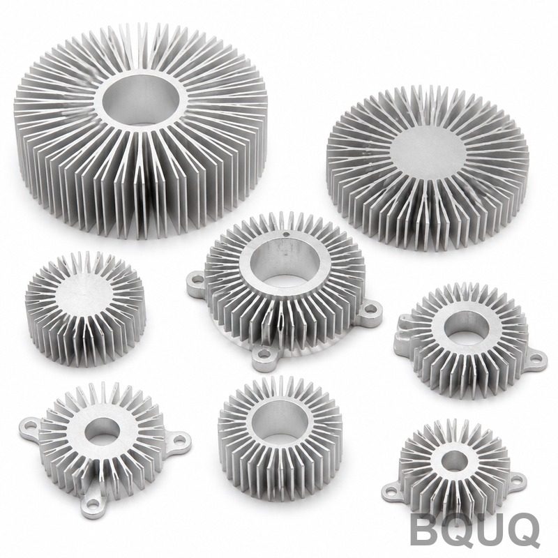
The decision to go custom should be based on quantifiable engineering criteria, not on aesthetic preference. Choose a custom profile when the calculated thermal resistance of a standard profile exceeds your target by more than 20%, or when the standard profile cannot fit the mounting hole pattern on your PCB or IGBT module. A custom profile is also justified when the ambient temperature is above 60°C, as this reduces the temperature differential and forces you to maximize surface area. For natural convection applications, custom profiles with a fin height to gap ratio above 8:1 and a base thickness of 8 mm or more can reduce the required heat sink length by 30% to 40% compared to a standard profile.
Another strong indicator is production volume. If you need more than 5,000 units per year, the custom tooling cost is typically recovered within 12 months through reduced fan requirements or lower material weight. Conversely, if you need fewer than 500 units, a standard profile with a simple clip-on fan is almost always the most cost-effective solution. Also, consider that custom profiles allow for the integration of a thermal pad groove or a thermocouple channel, which reduces assembly time and improves measurement accuracy. In our experience at BQUQ, 70% of custom profile requests are driven by space constraints in the final product enclosure, not by raw thermal load.
What Are the Typical Tolerances and Finishing Options?
Extrusion tolerances are governed by the EN 755-9 standard, and typical values are ±0.10 mm for fin thickness and ±0.15 mm for overall profile width. For critical mounting surfaces, a secondary CNC machining operation can achieve ±0.05 mm, but this adds USD 0.50 to USD 1.50 per piece. The standard extrusion surface finish is Ra 1.6 µm, which is suitable for most applications, but if the heat sink is visible, a clear anodize finish (10 to 15 µm thickness) is recommended for both aesthetics and corrosion protection. Black anodizing improves emissivity to 0.85, which enhances radiation heat transfer by up to 15% in natural convection scenarios.
For demanding applications, a hard anodize coating (25 to 50 µm) is available, though it reduces the effective fin gap by 0.05 mm per side and should be accounted for in the design. If you need to mount a fan or a power module, specify tapped holes or through-holes to be CNC machined after extrusion; the minimum thread size is M2.5, and the maximum depth is 3 times the thread diameter. Finally, consider a chemical bright dip or a brushed finish for cosmetic purposes, but note that these processes add 2 to 3 days to the lead time and are not recommended for heat transfer surfaces due to reduced emissivity.
FAQ
What Is the Minimum Fin Gap for an Extrusion Heat Sink Profile?
The minimum fin gap for a standard aluminum extrusion is 3.0 mm for 6063-T5 alloy; for 6061-T6, the minimum is 3.5 mm because the harder alloy requires more die pressure. A gap below 3.0 mm causes the aluminum to flow incompletely, leading to thin or missing fins. For gaps between 2.0 mm and 3.0 mm, a custom die with a specialized feeder design is required, increasing tooling cost by 30%.
Can Extrusion Heat Sinks Be Bent or Formed After Extrusion?
Yes, but only for profiles with a base thickness greater than 5 mm and a fin height less than 20 mm. Post-extrusion bending can be done to achieve a curved heat sink for LED luminaires, but the bending radius must be at least 10 times the profile height to prevent fin buckling. This process adds a tolerance of ±1.0 mm to the overall shape and is not recommended for profiles with fins on both sides.
How Does an Extrusion Heat Sink Compare to a Skived or Bonded Fin Heat Sink?
Extrusion heat sinks offer the lowest per-unit cost for high volumes (over 1,000 units) and are limited to a fin aspect ratio of 10:1. Skived fins can achieve a ratio of 40:1 and a fin thickness of 0.3 mm, but the tooling cost is USD 5,000 to USD 10,000 and the process is slower. Bonded fin heat sinks allow for a mixed fin material (e.g., copper fins on an aluminum base) but have a thermal interface resistance at the joint that can degrade performance by 10%.
What Is the Maximum Operating Temperature for a 6063-T5 Extrusion Heat Sink?
The maximum continuous operating temperature for 6063-T5 is 150°C, above which the temper begins to over-age and the yield strength drops below 100 MPa. For short-term exposure, the profile can withstand 200°C, but the thermal conductivity remains stable up to 300°C. If your application requires operation above 150°C, specify a T6 temper or consider a copper heat sink, though the cost will increase by 4 to 5 times.
Which Surface Finish Gives the Best Thermal Performance?
A bare, uncoated aluminum surface with a clean (degreased) finish has the lowest thermal resistance for convection, but it has a low emissivity of 0.05, which reduces radiation heat transfer. A black anodized finish (10 to 15 µm) increases emissivity to 0.85 and improves total heat dissipation by 10% to 15% in natural convection. Powder coating is not recommended for thermal surfaces because the thick layer (60 to 100 µm) acts as an insulator.
When Should I Use a Heat Pipe Inside an Extrusion Heat Sink?
You should integrate a heat pipe into an extrusion profile when the heat source area is smaller than 20% of the base plate area, or when the heat flux exceeds 50 W/cm². The heat pipe spreads the heat longitudinally before it reaches the fins, reducing the thermal resistance by 30% to 40% compared to a solid aluminum base. This is typically done by machining a groove in the base and using a thermally conductive epoxy to bond the heat pipe.
Can I Get a Prototype Extrusion Heat Sink Without Paying for Full Tooling?
Yes, but you will pay a premium per piece. Prototype machining from a solid block of aluminum (CNC milling) is the most common method, with a lead time of 3 to 5 days and a cost of USD 50 to USD 150 per piece for a simple profile. For a profile that must be extruded, a soft die (machined from a lower-grade steel) costs USD 800 to USD 1,200 and can produce 200 to 500 pieces before it wears out, which is ideal for pre-production validation.
Conclusion
The choice between standard and custom extrusion heat sink profiles is a balance of thermal performance, tooling investment, and production volume. Standard profiles are the default for low to medium power applications with generous space, while custom profiles deliver superior thermal resistance and integration when the envelope is tight or the heat flux is high. At BQUQ, we recommend starting with a thermal simulation of a standard profile, then comparing the cost delta of a custom die against the savings in fan size, heatsink length, or overall system weight. For a precise quotation, send your 2D or 3D CAD file, along with the heat load and allowable temperature rise, and our engineering team will respond within 12 hours with a tooling cost and lead time estimate. Contact us at sc@bquq.com, via WhatsApp at +86 13713157787, or visit www.bquq.com to start your project today.


