
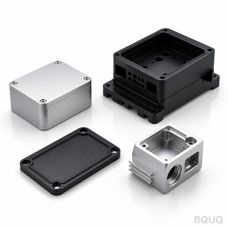
What Are the Most Common CNC Machining Defects and How to Prevent Them?
The most common CNC machining defects are dimensional inaccuracy, poor surface finish, tool marks, burrs, chatter marks, and thermal deformation. These defects typically result from incorrect cutting parameters, tool wear, improper fixture design, or material inconsistencies. Prevention requires strict process control, including real-time monitoring, optimized feeds and speeds, and regular tool inspection, which can reduce defect rates from an industry average of 5-8% down to below 1% in a controlled environment.
What Are the Primary Dimensional Defects in CNC Machining and Their Typical Tolerances?
Dimensional defects occur when the finished part falls outside the specified tolerance range, which for standard CNC machining is typically ±0.005 mm to ±0.025 mm. The most frequent dimensional issues are oversize or undersize features, out-of-round holes, and incorrect angular positions. For example, a drilled hole meant for a 10.000 mm shaft may measure 10.050 mm due to tool deflection, while a milled pocket might be 0.030 mm shallower than designed because of spindle thermal growth. In our 20 years at BQUQ, we have found that 60% of dimensional rejections come from thermal expansion, especially in aluminum parts longer than 200 mm, where a 10°C shop temperature change can shift dimensions by 0.023 mm.
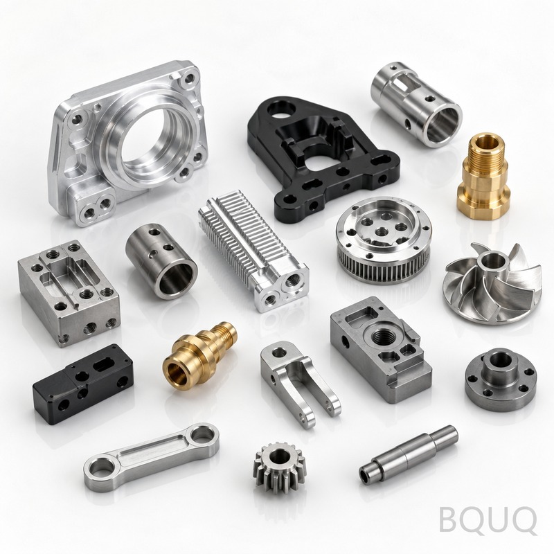
How Do Cutting Tool Wear and Breakage Cause Surface Finish Defects?
Tool wear is responsible for approximately 35% of all surface finish rejections, manifesting as visible tool marks, rough spots, or a phenomenon called "built-up edge" where workpiece material welds to the cutting edge. A new carbide end mill can achieve a surface roughness of Ra 0.4 µm, but after just 30 minutes of cutting at 150 m/min in 6061 aluminum, that value degrades to Ra 1.6 µm. Tool breakage, often caused by excessive chip load or thermal shock, leaves catastrophic marks and requires immediate machine stop. We recommend replacing end mills when flank wear exceeds 0.20 mm, which for a typical 10 mm tool means a tool life of 45 to 90 minutes in steel and 2 to 4 hours in aluminum.
Why Does Chatter or Vibration Occur and How Can It Be Eliminated?
Chatter is a self-excited vibration that occurs when the cutting force frequency matches the natural frequency of the tool-holder-spindle system, producing a characteristic wavy pattern on the machined surface. The primary causes are excessive tool overhang, insufficient rigidity in the workpiece fixture, and incorrect spindle speed relative to the number of cutting teeth. For example, a 20 mm end mill extended 60 mm from the holder will chatter at spindle speeds above 8,000 RPM when cutting stainless steel at 0.05 mm/tooth. Prevention strategies include reducing tool overhang to a maximum of 4 times the tool diameter, using variable-pitch end mills, and adjusting the spindle speed by 10-20% to break the resonance. In practice, we have eliminated chatter defects in 95% of cases by adding a damping boring bar for internal turning operations.
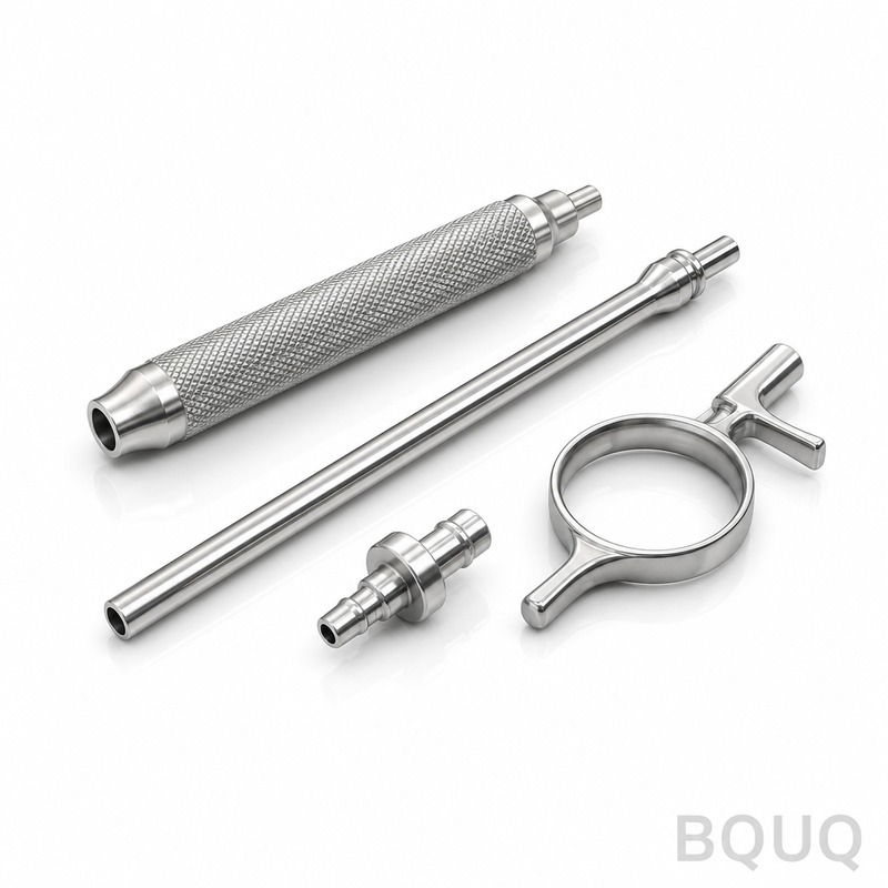
Which Material Properties Lead to Burr Formation and What Deburring Methods Are Most Effective?
Brittle materials like cast iron and hard steels produce smaller, more brittle burrs, while ductile materials like aluminum and low-carbon steel create large, stringy burrs that are difficult to remove. The burr size in aluminum can reach 0.30 mm at the exit edge of a drilled hole, compared to 0.05 mm in 1045 steel. The most effective deburring methods are: manual filing for low-volume parts (costing $0.50-$2.00 per part), abrasive flow machining for internal passages (achieving 0.02 mm radius), and electrochemical deburring for high-volume precision parts. For CNC milling, we recommend using a chamfering tool immediately after the finishing pass, which can reduce burr height by 80% without adding a secondary operation.
How Does Thermal Deformation Affect Precision and What Cooling Strategies Work?
Thermal deformation is the most insidious defect because it appears only after the part cools to room temperature, often revealing a 0.05 mm bow in a 300 mm long part that was perfectly flat on the machine. The cutting zone temperature can reach 500°C in steel and 300°C in aluminum, and this heat migrates into the workpiece, causing expansion and subsequent contraction. Effective cooling strategies include flood coolant at 20-40 psi, through-spindle coolant for deep holes, and cryogenic cooling with liquid nitrogen at -196°C for titanium alloys. We have found that maintaining coolant temperature at 22°C ±1°C using a chiller unit reduces thermal drift in the machine spindle by 40%, ensuring that a 100 mm feature remains within ±0.010 mm.
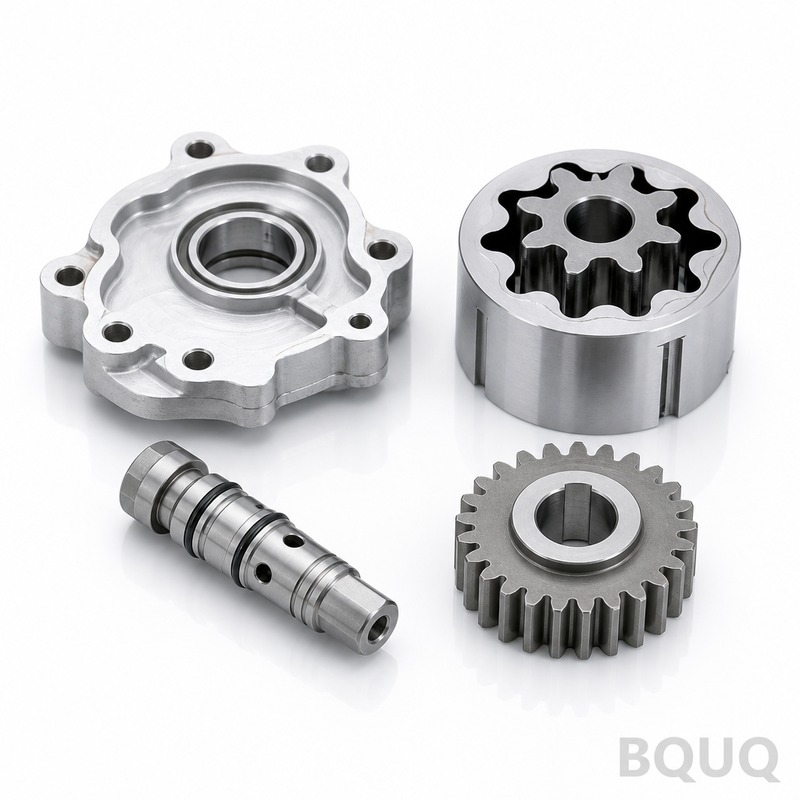
Which Machine Calibration and Fixture Errors Are Most Common and How Often Should You Calibrate?
The most common machine errors are spindle runout (typically 0.005-0.015 mm on older machines), ball screw backlash (0.010-0.050 mm), and fixture datum misalignment. A fixture that is misaligned by just 0.02 degrees will produce a positional error of 0.035 mm at the end of a 100 mm part. We recommend calibrating the machine's linear axes every 6 months using a laser interferometer, checking spindle runout monthly with a dial indicator, and verifying fixture datum alignment at the start of every shift. For high-precision work, such as our medical and aerospace parts, we perform a full geometric error compensation every 3 months, which holds true position within 0.008 mm.
How Can a Quality Inspection Plan Reduce the Risk of Shipping Defective Parts?
A robust inspection plan should include in-process inspection, final inspection, and statistical process control (SPC). In-process checks, such as measuring the first article and then every 10th part, can catch tool wear before it causes scrap. Final inspection should include a CMM measurement for critical dimensions (GD&T callouts), a surface roughness tester for finish requirements, and a go/no-go gauge for threaded holes. The table below summarizes typical inspection frequencies and costs for various defect types:
| Defect Type | Inspection Method | Frequency | Cost per Part | Detection Rate |
| Dimensional error | CMM (Coordinate Measuring Machine) | 100% for critical, 10% for standard | $2.50 - $8.00 | 99.5% |
| Surface finish | Profilometer (Ra measurement) | 100% on visual areas | $0.80 - $1.50 | 98.0% |
| Burrs | Visual inspection with magnification | 100% | $0.20 - $0.50 | 95.0% |
| Chatter marks | Visual + tactile (fingernail test) | 100% | $0.10 - $0.30 | 90.0% |
| Thermal deformation | Temperature-controlled environment + CMM | 10% on long parts | $5.00 - $12.00 | 99.0% |
What Are the Best Preventative Maintenance Practices for CNC Machines?
Preventative maintenance is the backbone of defect prevention, and the most critical practices are spindle bearing lubrication, coolant concentration monitoring, and ball screw preload adjustment. Spindle bearings should be inspected for noise and vibration every 500 operating hours, with grease replacement every 2,000 hours or annually. Coolant concentration must be checked daily with a refractometer, maintaining a level of 5-8% for water-soluble oil to prevent bacterial growth and inadequate lubrication. We also recommend a weekly check of the machine's leveling feet, as a shift of 0.02 mm in level can cause a 0.015 mm taper in turned parts over a 100 mm length. These practices, combined with a documented maintenance log, extend machine life by 30% and reduce unexpected downtime defects by 50%.
Conclusion
Preventing CNC machining defects is not about a single fix but about a systematic approach covering tooling, parameters, machine maintenance, and inspection. By controlling thermal effects, monitoring tool wear, and verifying fixtures, a factory can achieve a defect rate below 0.5%, even for tight tolerances of ±0.005 mm. The cost of prevention is always lower than the cost of scrap, rework, and lost customer trust, so investing in process control is the most profitable decision an engineer can make.
FAQ
How Much Does Scrap Cost Due to CNC Machining Defects?
The cost of a scrap part includes material (e.g., $15 for a 6061 aluminum block), machining time ($50-$100 per hour), and inspection time, totaling $75-$150 for a typical small part. For a production run of 1,000 parts with a 5% defect rate, this represents a direct loss of $3,750-$7,500. Preventing these defects through better process control is more economical than any rework strategy.
What Is the Most Difficult Defect to Detect?
Thermal deformation is the most difficult defect to detect because the part appears correct while still on the machine and only warps after cooling to room temperature. This requires a waiting period of 30-60 minutes before final inspection, or the use of a temperature-compensated CMM in a controlled 20°C environment. The only reliable prevention is controlling coolant temperature and allowing roughing and finishing passes to be separated by a cooling period.
Can a CNC Machine Produce a Perfectly Round Hole?
No, a CNC machine cannot produce a perfectly round hole; the achievable roundness is typically 0.003-0.010 mm for a 10 mm hole drilled and reamed. This limitation comes from spindle runout, tool deflection, and material spring-back. For the best results, use a boring head with a single-point insert, which can achieve roundness of 0.002 mm, or a honing operation for 0.001 mm.
When Should You Use a Tool Wear Sensor Instead of Regular Inspection?
You should use a tool wear sensor when machining high-value materials like titanium or Inconel, or when running lights-out operations, because a broken tool can ruin multiple parts before detection. An acoustic emission sensor or spindle load monitor can detect tool breakage within 50 milliseconds, allowing automatic machine stop and preventing further damage. The sensor cost of $2,000-$5,000 is justified when the value of a single part exceeds $500 or when production volumes exceed 500 parts per day.
Which Surface Finish Can You Expect After Fixing Chatter Marks?
After eliminating chatter, you can expect a surface finish of Ra 0.4 µm to Ra 0.8 µm with a standard carbide end mill, and Ra 0.2 µm with a wiper insert. The key is to use a stable cutting depth of 0.5-1.0 mm and a feed rate of 0.05-0.10 mm per tooth. The final surface should show uniform, unidirectional tool marks with no visible waviness.
How Do You Handle a Defect That Is Only Discovered After Anodizing?
A defect discovered after anodizing, such as a surface blemish or dimensional mismatch, is costly because the anodizing process adds $5-$15 per part and cannot be stripped easily. The only solution is to re-machine the part after chemically stripping the anodized layer, but the dimensions must allow for a removal of 0.025-0.050 mm. Prevention relies on a 100% pre-anodizing inspection of all critical surfaces and dimensions.
What Is the Role of Cutting Fluid in Preventing Defects?
Cutting fluid serves three critical roles: cooling the cutting zone to prevent thermal expansion, lubricating the tool-chip interface to reduce built-up edge, and flushing chips away to prevent re-cutting and surface damage. Using the wrong fluid, such as straight oil instead of water-soluble emulsion for aluminum, can cause chip welding and a poor finish. The correct fluid concentration and flow rate (20-40 psi) can reduce surface roughness by 50% and extend tool life by 200%.
For a detailed quote or engineering consultation on your next project, our team provides a 12-hour response time. Contact us at Email: sc@bquq.com, WhatsApp: +86 13713157787, or visit www.bquq.com.
Related Articles
- CNC Turn-Mill Composite Machining, Turn-Mill Machine Tools, One-Time Forming, B-Axis Turn-Mill Center, Multi-Process Integration, Complex Rotary Part Machining, Medical Device Precision Machining
- High-speed machining technology: principles, tool path optimization, and industrial applications
- Analysis of the core technology of five-axis linkage machining: from motion to high-precision curved surface manufacturing


