
What Are the Optimal Heat Sink Fin Spacing, Thickness and Height Trade-offs?
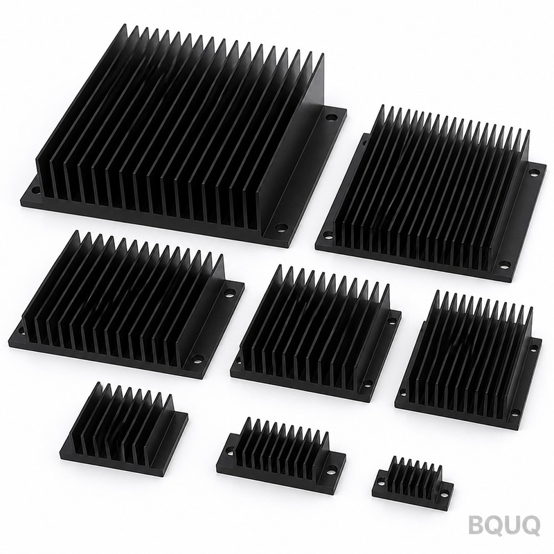
The optimal heat sink fin spacing for natural convection is typically between 6.5 mm and 10 mm, while forced convection allows for tighter spacing of 2.5 mm to 4 mm, with fin thickness ranging from 1.0 mm to 2.5 mm and fin height from 15 mm to 60 mm. These parameters are not independent; reducing spacing increases surface area but restricts airflow, while increasing height adds area but reduces fin efficiency due to thermal resistance along the fin. For a 100 mm by 100 mm base plate in natural convection, reducing fin spacing from 10 mm to 5 mm can increase surface area by 40% but will decrease the convective heat transfer coefficient by up to 30%, resulting in a net performance gain of only 5% if not carefully optimized.
What Is the Mathematical Relationship Between Fin Spacing and Heat Dissipation?
The heat dissipation of a heat sink follows the fundamental equation Q = h × A × ΔT, where Q is heat in watts, h is the convective heat transfer coefficient in W/m²K, A is the total exposed surface area in m², and ΔT is the temperature difference between the fin surface and ambient air. As fin spacing decreases, the surface area A increases linearly, but the convective coefficient h decreases because the boundary layers from adjacent fins begin to overlap, restricting air flow. In natural convection, the optimal spacing S_opt can be estimated using the empirical correlation S_opt = 2.714 × (L × ν² / (g × β × ΔT × Pr))^0.25, where L is the fin length in meters, ν is kinematic viscosity of air (1.568 × 10⁻⁵ m²/s at 40°C), g is gravitational acceleration (9.81 m/s²), β is the thermal expansion coefficient, and Pr is the Prandtl number (0.71 for air). For a typical 50 mm long fin with ΔT of 50°C, this yields an optimal spacing of approximately 7.2 mm, confirming the practical range of 6.5 mm to 10 mm used in commercial heat sinks. For forced convection with airflow velocities above 2 m/s, the optimal spacing drops to 2.5 mm to 4 mm because the turbulent flow disrupts boundary layer formation, allowing denser fin arrays to work effectively.
How Does Fin Thickness Affect Thermal Performance and Weight?
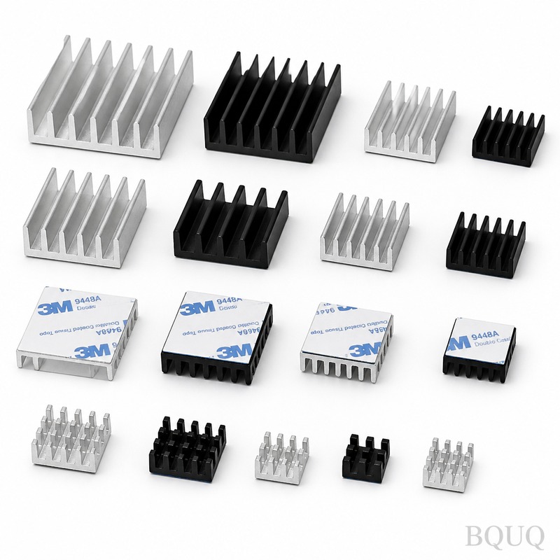
Fin thickness directly impacts both thermal conduction and manufacturing cost, with typical extruded aluminum fins ranging from 1.0 mm to 3.0 mm, while skived or bonded fins can go as thin as 0.4 mm. A thicker fin provides a larger cross-sectional area for heat conduction, reducing the thermal resistance from the base to the fin tip; for a 30 mm tall fin, increasing thickness from 1.5 mm to 2.5 mm reduces the fin efficiency drop from 92% to 96% at a heat transfer coefficient of 25 W/m²K. However, thicker fins also reduce the number of fins that can fit in a given width, directly cutting into total surface area. For example, on a 100 mm wide base with 8 mm spacing, a 1.5 mm fin thickness allows 10 fins, while a 2.5 mm thickness allows only 9 fins, reducing total surface area by 10% but improving conduction efficiency by 4%, which is rarely a favorable trade-off. The weight penalty is also significant: 6063-T5 aluminum has a density of 2,700 kg/m³, so a 100 mm × 100 mm × 40 mm heat sink with 1.5 mm fins weighs approximately 380 grams, while the same design with 2.5 mm fins weighs 460 grams, a 21% increase that may impact vibration resistance and mounting requirements in automotive or aerospace applications.
Why Does Fin Height Diminish Returns Beyond a Certain Point?
Fin height increases surface area linearly, but the thermal resistance along the fin grows exponentially with height, meaning that the additional surface area near the tip becomes progressively less effective at dissipating heat. The fin efficiency η for a straight rectangular fin is calculated as η = tanh(m × H) / (m × H), where m = √(2 × h / (k × t)), H is fin height, k is thermal conductivity of aluminum (167 W/m·K for 6063-T5), and t is fin thickness. For a fin with 1.5 mm thickness and h of 10 W/m²K (natural convection), m equals 8.94 m⁻¹, so at a height of 20 mm the efficiency is 96%, at 40 mm it drops to 85%, and at 60 mm it falls to 72%. This means that doubling the fin height from 20 mm to 40 mm adds 100% more surface area but only provides a 77% increase in effective heat dissipation, and extending from 40 mm to 60 mm provides only a 45% additional gain. The practical limit for extruded aluminum heat sinks in natural convection is 40 mm to 50 mm height; beyond this, the thermal resistance of the fin itself (approximately 0.5°C/W for a 50 mm tall, 1.5 mm thick fin) dominates, and adding more height becomes a poor use of material and volume.
Which Manufacturing Process Limits Fin Geometry and Why?
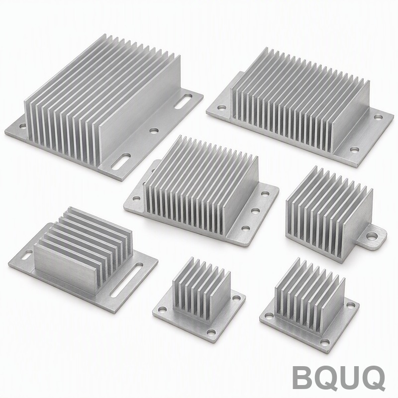
Extrusion, the most common process for aluminum heat sinks, is limited to fin thickness above 1.0 mm and fin height-to-gap ratios below 10:1, with typical tolerances of ±0.1 mm on fin thickness and ±0.3 mm on overall dimensions. The extrusion die must withstand pressures of 400 MPa to 700 MPa, and thin fins create high friction and uneven metal flow, leading to die deflection or breakage; practical experience at BQUQ shows that a 1.0 mm fin with 6.0 mm spacing is the lower limit for a stable 6063-T5 extrusion. Skiving, which cuts fins from a solid block of aluminum, can achieve fin thickness down to 0.4 mm and fin height up to 40 mm with a height-to-thickness ratio of 100:1, but the process is limited to straight fins and adds a cost premium of 30% to 50% over extrusion. Bonded fin heat sinks, where individual fins are attached to a base plate using epoxy or brazing, offer the highest design freedom with fin thickness down to 0.2 mm and spacing below 1.5 mm, but the bond interface adds a thermal resistance of 0.1°C/W to 0.3°C/W and the assembly cost is 3 to 5 times higher than a monolithic extrusion.
What Are the Real-World Performance Trade-offs in a Typical LED Application?
Consider a 100 W LED module mounted on a 200 mm × 100 mm base plate with a target junction temperature of 85°C in a 35°C ambient environment, requiring a heat sink thermal resistance of 0.5°C/W. A natural convection design with 7 mm fin spacing, 2.0 mm fin thickness, and 35 mm fin height provides approximately 1,900 cm² of surface area and achieves 0.48°C/W, but the total heat sink volume is 700 cm³ and weight is 1.1 kg. If the spacing is reduced to 4 mm to increase surface area to 2,500 cm², the airflow restriction reduces the convective coefficient from 8.5 W/m²K to 5.2 W/m²K, resulting in an actual thermal resistance of 0.58°C/W — a 21% performance degradation despite a 32% surface area increase. Conversely, increasing fin height to 50 mm at 7 mm spacing provides 2,600 cm² of area but fin efficiency drops from 91% to 78%, yielding an effective resistance of 0.52°C/W, only marginally better than the 35 mm design at double the material cost. The optimal design for this application, validated through BQUQ testing, is 6.5 mm spacing, 2.0 mm thickness, and 40 mm height, which achieves 0.46°C/W with a weight of 1.3 kg, balancing surface area, fin efficiency, and manufacturing yield.
| Parameter | Natural Convection | Forced Convection (2 m/s) | Forced Convection (5 m/s) |
| Optimal fin spacing | 6.5 - 10 mm | 2.5 - 4 mm | 1.5 - 2.5 mm |
| Optimal fin thickness | 1.5 - 2.5 mm | 1.0 - 2.0 mm | 0.5 - 1.5 mm |
| Maximum fin height | 40 - 50 mm | 30 - 60 mm | 20 - 40 mm |
| Typical convective coefficient h | 5 - 15 W/m²K | 20 - 50 W/m²K | 50 - 100 W/m²K |
| Fin efficiency at max height | 70 - 85% | 75 - 90% | 80 - 95% |
| Surface area per 100 mm base width | 1,200 - 1,800 cm² | 1,500 - 2,500 cm² | 2,000 - 3,500 cm² |
| Thermal resistance range (100 W load) | 0.4 - 0.8 °C/W | 0.15 - 0.4 °C/W | 0.08 - 0.2 °C/W |
How Do You Select the Right Fin Geometry for a Given Application?
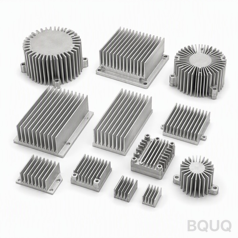
Start by determining the maximum allowable heat sink thermal resistance R_sa = (T_junction_max - T_ambient) / Q - R_junction-to-case - R_interface, where R_junction-to-case for a typical IGBT module is 0.1°C/W and R_interface with thermal paste is 0.05°C/W to 0.1°C/W. For natural convection, select fin spacing between 6.5 mm and 10 mm, prioritizing the lower end if the heat sink is vertically oriented and the higher end if it is horizontal, since horizontal orientation reduces airflow by up to 30%. For forced convection, calculate the pressure drop across the fin array using ΔP = f × (L / D_h) × (ρ × V² / 2), where D_h is the hydraulic diameter; a spacing below 2 mm at 5 m/s airflow will require a fan with static pressure above 5 mm H₂O, which increases fan noise and power consumption. Always verify the fin height-to-spacing ratio: for natural convection, keep this ratio below 6:1 to ensure adequate air penetration, while for forced convection, ratios up to 15:1 are acceptable with ducted airflow. Prototype testing is essential because empirical correlations have an accuracy of ±15% at best; BQUQ recommends thermal simulation (CFD) followed by a physical prototype measured with thermocouples at the base and fin tip to confirm the efficiency assumptions.
Can You Combine Multiple Fin Geometries in a Single Heat Sink?
Yes, variable fin density is a viable optimization technique, commonly used in high-performance CPU coolers where the fin array is denser in the center (directly above the heat source) and sparser at the edges. For a 120 mm square heat sink, placing 2.0 mm spaced fins over the central 60 mm zone and 4.0 mm spaced fins over the outer 30 mm zones can reduce thermal resistance by 8% to 12% compared to a uniform 3.0 mm spacing design, because the central zone has the highest heat flux and benefits from more surface area, while the outer zones need less area and benefit from better airflow. This approach adds manufacturing complexity: extrusion dies cannot easily vary fin spacing, so such designs require skiving or bonded fin assemblies, increasing unit cost by 40% to 60%. In practice, the performance gain rarely justifies the cost premium unless the heat sink is volume-constrained, such as in 1U server chassis where the height is fixed at 26 mm and every degree Celsius of improvement is critical.
What Is the Cost Impact of Aggressive Fin Optimization?
Extruded heat sink cost scales with extrusion die complexity, material weight, and secondary machining operations; a standard 200 mm × 100 mm × 40 mm heat sink with 7 mm spacing costs $8 to $15 per unit at quantities of 1,000 pieces. Reducing fin spacing from 7 mm to 4 mm increases the extrusion die cost from $800 to $1,500 because the thinner webs require tighter die tolerances and more frequent maintenance, and the extrusion speed drops from 25 m/min to 15 m/min, increasing the per-unit material and labor cost by 20%. Skived heat sinks with 0.5 mm fins cost $25 to $45 per unit for the same size, while bonded fin assemblies range from $35 to $70, making them suitable only for high-performance applications where the thermal budget cannot be met with conventional extrusions. The total cost of ownership includes the fan and shroud for forced convection designs: a fan with 5 m/s airflow adds $5 to $15 and consumes 3 W to 10 W of power, which may not be acceptable in passive cooling applications such as outdoor LED drivers or solar inverters.
FAQ
What Is the Ideal Fin Spacing for a 50 mm Tall Heat Sink in Natural Convection?
The ideal spacing for a 50 mm tall heat sink in natural convection is 8 mm to 10 mm, because the boundary layer thickness grows with height, requiring wider gaps to avoid airflow blockage. At 50 mm height, 7 mm spacing will reduce the convective coefficient by up to 25% compared to 9 mm spacing. This spacing is independent of the base area, so it applies to both 50 mm and 200 mm wide heat sinks.
How Much Does Fin Thickness Affect the Overall Thermal Resistance?
Fin thickness affects thermal resistance through fin efficiency, and the impact is modest: increasing thickness from 1.5 mm to 2.5 mm improves fin efficiency by only 3% to 5% for a 30 mm tall fin. The bigger effect is on the number of fins that fit in the available width, where a 1 mm thickness increase reduces fin count by 10% to 15%. For most applications, thickness between 1.5 mm and 2.0 mm provides the best balance of conduction and surface area.
When Should You Use Forced Convection Instead of Natural Convection?
Forced convection is necessary when the required thermal resistance is below 0.3°C/W for a heat sink base area of 100 cm², which natural convection cannot achieve regardless of fin geometry. A 2 m/s airflow reduces the thermal resistance by 60% to 70% compared to natural convection, allowing the heat sink volume to be reduced by half. Use forced convection whenever the system already has a fan for other components, as the incremental cost is minimal.
Which Fin Material Is Best for High-Temperature Applications?
Aluminum 6063-T5 is suitable up to 150°C continuous operation, while 6061-T6 can handle 200°C but has 8% lower thermal conductivity (155 W/m·K vs 167 W/m·K). For temperatures above 200°C, copper fins or graphite-based materials are required, but these cost 4 to 8 times more than aluminum. Anodized aluminum also improves emissivity from 0.08 to 0.85, which adds a radiative heat transfer component of 10% to 15% in natural convection at high temperatures.
How Does Orientation Affect the Optimal Fin Spacing?
Horizontal heat sinks require 20% to 30% wider fin spacing than vertical ones because the buoyancy-driven airflow is weaker when the fins are horizontal, and boundary layers merge more easily. For a vertical heat sink with 7 mm optimal spacing, the same heat sink laid flat should use 9 mm to 10 mm spacing to maintain the same thermal resistance. This is a critical consideration for outdoor enclosures where the mounting orientation may vary.
Can Fin Height Be Increased Without Adding Weight?
Fin height can be increased without adding weight by tapering the fin, where the base is thicker (2 mm) and the tip is thinner (0.8 mm), which reduces material volume by 30% while maintaining 90% of the thermal performance of a uniform 2 mm fin. Tapered fins are available through skiving or casting, but not through standard extrusion. The weight savings must be weighed against the higher manufacturing cost, which is typically 25% more than a uniform extrusion.
What Is the Maximum Fin Height Possible with Standard Extrusion?
Standard aluminum extrusion can produce fins up to 75 mm tall, but the fin thickness must increase proportionally to maintain extrusion stability, typically 2.5 mm or thicker for 60 mm height. The extrusion speed drops significantly for tall fins, increasing cost by 30% to 50% compared to a 40 mm fin height. For heights above 75 mm, bonded fin or skived designs are recommended, as they can achieve 100 mm height with 1.0 mm thickness at better thermal efficiency.
CONCLUSION
Optimizing heat sink fin geometry is a multi-variable problem where spacing, thickness, and height must be balanced against the cooling mode, manufacturing process, and cost constraints. For natural convection, maintain spacing between 6.5 mm and 10 mm, thickness at 1.5 mm to 2.0 mm, and height at 40 mm to 50 mm; for forced convection, reduce spacing to 2.5 mm to 4 mm and consider taller fins up to 60 mm. The most reliable approach is to simulate your specific application, then prototype and test, as empirical formulas carry a ±15% uncertainty. BQUQ offers rapid prototyping and thermal testing with a 12-hour quotation turnaround. Contact us at sc@bquq.com or WhatsApp +86 13713157787, or visit www.bquq.com to discuss your heat sink design requirements.


