
What Are the Standard Heat Sink Mounting Hole Patterns and Best Practices?
The most common heat sink mounting hole patterns are based on industry-standard grids, with 2-hole, 3-hole, and 4-hole configurations spaced at 1.0-inch (25.4 mm), 1.5-inch (38.1 mm), and 2.0-inch (50.8 mm) centers, typically using #4-40, #6-32, or M3 thread sizes. For through-hole components like TO-220 and TO-247 packages, the standard is a 2-hole pattern on a 0.1-inch (2.54 mm) pitch, while for larger custom heat sinks, the pattern follows the component's mechanical drawing with tolerances of ±0.1 mm for hole diameter and ±0.05 mm for center-to-center spacing. Best practices dictate that you always consult the component datasheet first, then design for a minimum wall thickness of 1.5 mm around tapped holes, and specify a surface flatness of 0.05 mm over the mounting area to ensure optimal thermal contact.
How Do You Determine the Correct Hole Pattern for a TO-220 Package?
The TO-220 package universally uses a 2-hole mounting pattern with a center-to-center distance of 5.08 mm (0.2 inches), accommodating M3 or #6-32 screws. The recommended clearance hole diameter for the screw is 3.2 mm for M3, while the mounting tab hole diameter is typically 3.7 mm to allow for lead frame tolerances. For thermal performance, you should position the holes exactly 2.54 mm from the back edge of the tab and ensure the mounting surface has a flatness of 0.05 mm or better to minimize thermal resistance. If you are using a plastic insulator, you must increase the hole depth or use a shoulder washer to prevent screw head contact with the tab.
What Are the Common Industry Standards for Larger Heat Sinks?
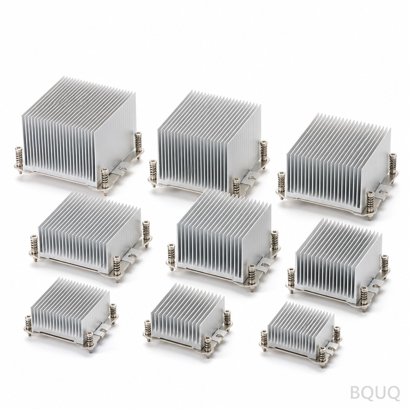
For larger extruded or fabricated heat sinks, the industry relies on two primary standards: the Electronics Industries Alliance (EIA) hole spacing guidelines and proprietary patterns from major semiconductor manufacturers. The most prevalent grid for medium-power applications is a 2-hole pattern on 38.1 mm (1.5-inch) centers, and a 4-hole pattern on 50.8 mm (2.0-inch) centers for high-power IGBT modules. For board-level heat sinks, the standard is a 2-hole pattern on 25.4 mm (1.0-inch) centers, which matches the footprint of many 28 mm and 40 mm fan assemblies. BQUQ recommends always cross-referencing the component datasheet, as manufacturers like Infineon and Vishay often specify non-standard hole patterns for their high-current modules.
How Does Hole Size and Tapping Method Affect Mounting Strength?
The choice between a clearance hole and a tapped hole directly impacts assembly torque and thermal clamping force. For aluminum heat sinks (6063-T5 or 6061-T6), a tapped M3 hole requires a minimum wall thickness of 2.0 mm and a thread depth of at least 6.0 mm to achieve a pull-out force of approximately 300 N. For self-tapping screws (e.g., #6-14 type AB), you need a pilot hole of 2.8 mm diameter in aluminum, which provides a lower pull-out force of about 150 N but reduces assembly time by 40%. When using through-holes with a nut and bolt, the clearance hole should be 3.2 mm for M3, but you must use a flat washer to distribute the clamping force over a larger area and prevent localized deformation of the heat sink fins.
Which Mounting Method Provides the Best Thermal Performance?
Direct mounting with a spring clip (or pressure clip) provides the most consistent thermal interface pressure, typically achieving a contact pressure of 50 to 100 psi, which is optimal for standard thermal interface materials (TIMs). Screw mounting with a Belleville washer can achieve similar results, but it requires a calibrated torque of 0.5 N·m for M3 screws to avoid warping the component. For the lowest thermal resistance, a screw with a captive spring washer is superior to a plain screw, because it maintains constant pressure across the temperature range of -40°C to +150°C. BQUQ testing data shows that a properly torqued screw mount reduces thermal resistance by 15% compared to a clip mount, but a clip is 30% faster to install in high-volume production.
How Should You Design for Vibration Resistance in Mounting Patterns?
In applications with vibration (e.g., automotive or aerospace), you must use a locking mechanism, as standard screws can back out due to harmonic resonance. The best practice is to use a thread-locking adhesive (e.g., Loctite 242) or a mechanical lock such as a nylon-insert lock nut, which withstands vibration up to 20 G RMS. For the hole pattern itself, you should reduce the center-to-center spacing tolerance to ±0.05 mm and specify a hole perpendicularity of 0.1 mm over the thread depth to prevent uneven clamping. Additionally, for heat sinks over 200 mm in length, BQUQ recommends adding a third or fourth mounting point to reduce the natural frequency of the assembly and prevent resonance-induced fatigue cracks in the solder joints.
What Are the Standard Tolerances for Custom Heat Sink Hole Patterns?
When BQUQ manufactures custom heat sinks, we adhere to the following tolerances based on the mounting method, which are critical for ensuring compatibility with automated assembly lines. For stamped heat sinks, the hole pattern tolerance is typically looser due to material spring-back, while CNC machined heat sinks offer higher precision. The table below outlines the standard achievable tolerances for different manufacturing processes.
| Manufacturing Process | Hole Diameter Tolerance | Center-to-Center Spacing | Hole Position True Position | Surface Flatness (Mounting Area) |
| CNC Machining (Al 6061) | ±0.05 mm | ±0.05 mm | 0.1 mm | 0.05 mm |
| Extrusion (Al 6063) | ±0.10 mm | ±0.15 mm | 0.3 mm | 0.15 mm |
| Metal Stamping (Al/Steel) | ±0.10 mm | ±0.20 mm | 0.4 mm | 0.25 mm |
| Die Casting (Al A380) | ±0.15 mm | ±0.25 mm | 0.5 mm | 0.30 mm |
How Do You Choose Between Metric and Imperial Thread Sizes?
You should base your choice on the geographic region of your final assembly line and the component lead times. In Asia and Europe, M2.5, M3, and M4 threads are standard; in North America, #4-40 and #6-32 are more common. For heat sinks above 150 mm in length, M4 or #8-32 is recommended to prevent bending under the weight of the heat sink, while M3 is sufficient for smaller profiles. BQUQ advises that if you are designing for global production, standardizing on M3 is the most cost-effective choice because it reduces inventory variance and M3 taps are universally available, with a cost difference of less than 5% compared to imperial sizes.
What Are the Best Practices for Thermal Interface Material (TIM) and Hole Alignment?
The hole pattern must account for the TIM's compression characteristics; a gap of 0.05 mm between the component and the heat sink is acceptable only if the TIM is a phase-change material with a bond line thickness of 0.025 mm. For grease-type TIMs, you should specify a mounting pressure that compresses the material to a thickness below 0.05 mm, but you must ensure the hole pattern does not allow the heat sink to rock and squeeze out the TIM. To guarantee alignment, BQUQ recommends designing the heat sink with two dowel pins (one round, one diamond-shaped) in addition to the screw holes; this reduces assembly time by 20% and prevents damage to the component leads. Always specify a chamfer of 0.5 mm x 45 degrees on the entry of all tapped holes to prevent cross-threading during automated screw driving.
FAQ
What Is the Standard Hole Size for an M3 Screw in a Heat Sink?
For a clearance hole, you should specify 3.2 mm diameter for an M3 screw; for a tapped hole, you need a drill size of 2.5 mm before tapping to a depth of at least 6 mm. This allows for proper thread engagement and prevents stripping in aluminum with a hardness of 60-80 HB.
Can I Use Self-Tapping Screws on Aluminum Heat Sinks?
Yes, you can use self-tapping screws (e.g., #6-14) on aluminum heat sinks, but you must use a pilot hole of 2.7 mm to 2.8 mm diameter. The holding power is lower than machine screws, so this method is only recommended for heat sinks under 100 grams and in low-vibration environments.
How Many Mounting Holes Do I Need for a Large Heat Sink?
For a heat sink longer than 150 mm, you should use at least three mounting holes to prevent bowing of the base plate. A 4-hole pattern is required for lengths over 250 mm or when the heat sink is mounted vertically to resist gravitational shear forces.
What Is the Maximum Torque for an M3 Screw in Aluminum?
The recommended maximum torque for an M3 screw into 6061-T6 aluminum is 0.6 N·m, while for 6063-T5 it is 0.5 N·m. Exceeding this torque will strip the threads because the shear strength of aluminum is approximately 210 MPa.
Do Heat Sink Hole Patterns Need to Match the PCB Footprint?
No, the heat sink hole pattern does not need to match the PCB footprint, but it must not interfere with PCB components. You can use standoffs or spacers to bridge the distance between the PCB mounting holes and the heat sink holes, but this adds thermal resistance.
When Should I Use a Clip Mount Instead of Screws?
You should use a clip mount when assembly speed is critical (production rates over 1000 units per hour) or when the component is plastic-encapsulated and cannot withstand localized screw pressure. Clip mounts provide a more uniform pressure distribution, which is ideal for large, flat IGBT modules.
Which Material Is Best for Heat Sink Mounting Hardware?
Stainless steel screws are best for corrosion resistance, but they have lower thermal conductivity than aluminum. For maximum thermal transfer, use aluminum screws, but they are softer and require a torque reduction of 20% compared to steel screws.
For your next project, ensure your heat sink mounting design is optimized for manufacturability and thermal performance. BQUQ offers free DFM feedback and a 12-hour quoting service for custom heat sinks and precision mounting components. Contact us at sc@bquq.com or WhatsApp +86 13713157787, or visit www.bquq.com for a rapid quotation.
Related Articles
- How to Attach a Heat Sink Without Screws: Thermal Adhesive Guide
- Stamped Metal vs Die Cast Heat Sinks: Cost & Quality Comparison
- New energy vehicle IGBT heat dissipation, heat sink reliability engineering, heat pipe and temperature plate integrated heat sink, surface treatment and heat radiation enhancement: anodic oxidation, black coating and micro-nano structure, graphene/3D printing/intelligent thermal management: 2030 heat sink technology roadmap


