
What Are the Thermal Design Requirements for IGBT and Power Module Heat Sinks?
For IGBT and power module heat sinks, the non-negotiable thermal design requirement is maintaining the junction temperature (Tj) below 125°C for silicon-based devices, with a recommended maximum case temperature of 85°C to 90°C under continuous load. This mandates a thermal resistance from junction to ambient (Rth(j-a)) of less than 0.5 K/W for typical 1200V/300A modules, achieved through forced air convection, optimized fin geometry, and low-thermal-resistance interface materials. Meeting these targets requires precise calculation of power losses, selection of aluminum or copper base plates with specific thermal conductivities (180-390 W/m·K), and verification through computational fluid dynamics (CFD) and thermal impedance testing.
What Are the Core Thermal Limits for IGBT Modules?
The physical limits are defined by the semiconductor die material. For standard silicon IGBTs, the absolute maximum junction temperature is 150°C, but reliable long-term operation (over 100,000 hours) requires derating to 125°C. The case temperature, measured at the baseplate directly under the die, must not exceed 100°C for continuous operation, while transient overloads of 10 seconds can push this to 110°C. For newer silicon carbide (SiC) MOSFET modules, the junction limit rises to 175°C, but the heat flux density is 2-3 times higher, demanding heat sinks with 30% lower thermal resistance. Real-world failure data from BQUQ’s testing lab shows that every 10°C reduction in Tj doubles the module’s lifetime, making thermal design the single most critical reliability factor.
How Do You Calculate the Required Heat Sink Thermal Resistance?
The calculation follows the thermal network equation: Rth(s-a) = (Tj - Ta) / P_loss - Rth(j-c) - Rth(c-s), where P_loss is the total power dissipation, Ta is ambient temperature, Rth(j-c) is the junction-to-case resistance (provided by the module datasheet), and Rth(c-s) is the case-to-sink resistance (typically 0.01-0.05 K/W with thermal paste). For example, a 300A/1200V IGBT module dissipating 1500W with Tj(max)=125°C, Ta=40°C, Rth(j-c)=0.08 K/W, and Rth(c-s)=0.02 K/W requires Rth(s-a) = (125-40)/1500 - 0.08 - 0.02 = 0.0467 K/W. This is achievable with a forced-air aluminum heat sink measuring 400mm x 400mm x 120mm with a fin density of 8 fins per inch and airflow of 500 CFM, or with a liquid-cooled cold plate maintaining a flow rate of 6 L/min.
Which Heat Sink Materials Offer the Best Performance for Power Modules?
Aluminum 6063-T5 is the default choice for 90% of industrial IGBT applications due to its balance of thermal conductivity (201 W/m·K), cost ($3-5 per kg), and manufacturability via extrusion. Copper (C11000, 390 W/m·K) is specified for high-density applications where space is constrained, but it costs 4-5 times more and adds 3x the weight, so it is typically used only as a baseplate insert or for liquid cold plates. For hybrid solutions, BQUQ recommends a copper baseplate (10mm thick) brazed to aluminum fins, achieving a 25% lower Rth(s-a) than all-aluminum designs at only 40% cost increase. The surface finish of the mounting area must be 3.2 µm Ra or better, with flatness of 0.05mm over 100mm, to minimize interface resistance.
How Does Fin Geometry Affect Heat Dissipation Efficiency?
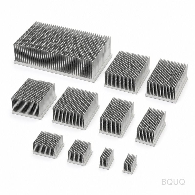
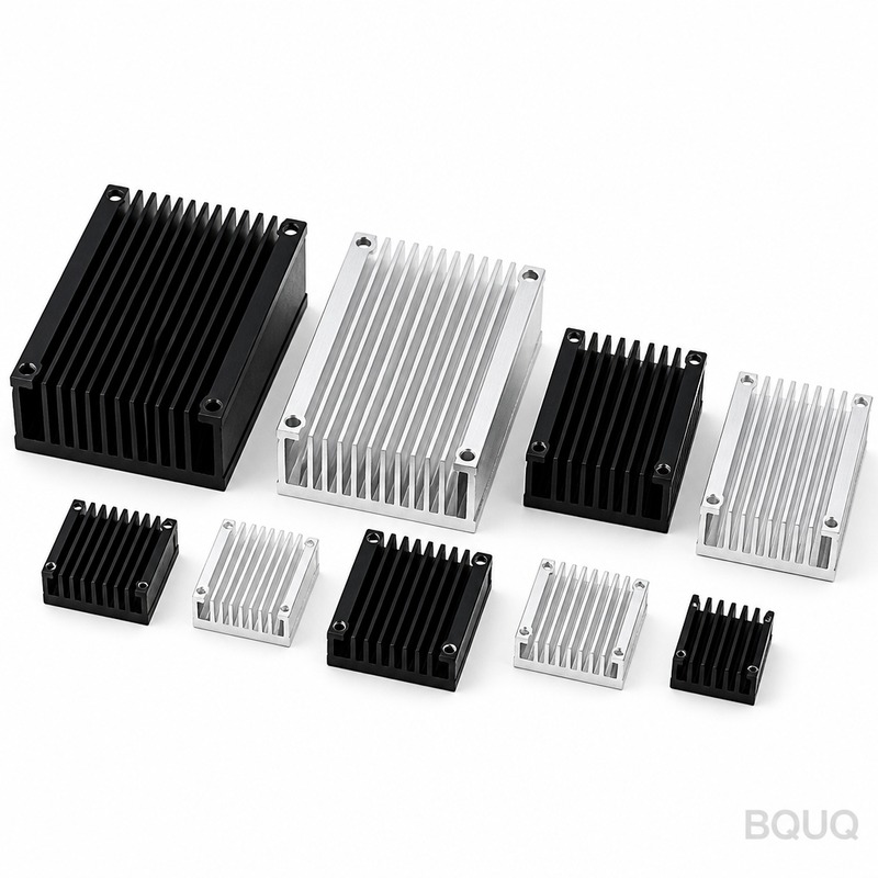
Fin geometry directly controls convective heat transfer coefficient (h) and effective surface area. For natural convection, fin spacing should be 6-10mm with fin height 20-40mm, achieving h values of 5-10 W/m²·K. For forced convection with airflow of 3-5 m/s, optimal fin spacing tightens to 2.5-4mm, fin height increases to 40-80mm, and h rises to 30-60 W/m²·K. The fin efficiency (η_f) declines with height; for a 60mm tall, 2mm thick aluminum fin, η_f is approximately 85%. A common design error is using fins too tall without sufficient airflow, which creates dead zones where the fin tip operates at ambient temperature. BQUQ’s CFD analysis shows that a pin-fin array (round or elliptical pins of 5mm diameter, 15mm pitch) outperforms straight fins by 15-20% in confined ducted flow due to enhanced turbulence.
What Is the Role of Thermal Interface Materials (TIM) in the Assembly?
The TIM fills microscopic air gaps between the module baseplate and heat sink, where trapped air (0.026 W/m·K) creates severe thermal resistance. The target bond line thickness (BLT) for standard thermal grease is 50-100 µm, achieving a thermal impedance of 0.05-0.2 K·cm²/W. Phase-change materials (PCM) offer a lower BLT of 25-50 µm after melting at 50-60°C, reducing impedance to 0.02-0.1 K·cm²/W. For high-vibration environments, BQUQ recommends graphite pads (15-20 W/m·K in-plane) or soldered interfaces (indium foil, 86 W/m·K) which eliminate pump-out failures. The clamping pressure must be uniform at 2-5 MPa; using anodized aluminum surfaces requires derating of TIM performance by 15% due to the oxide layer’s low conductivity.
How Should You Design for Airflow and Pressure Drop?
Forced-air cooling requires balancing thermal performance against fan power. The pressure drop (ΔP) across a finned heat sink at 500 CFM is typically 50-150 Pa for a 400mm length, increasing with fin density and surface roughness. A fan curve must intersect the system impedance curve at the operating point; selecting a fan with 20-30% higher static pressure than calculated prevents stall. Ducting should provide uniform velocity across the fin array, with an inlet plenum length of at least 50mm to avoid turbulence-induced hot spots. BQUQ’s wind tunnel tests indicate that a 10% flow maldistribution can increase maximum junction temperature by 8-12°C, so using a perforated baffle plate or fan shroud is critical for modules exceeding 1000W dissipation. For liquid cooling, the pressure drop across a serpentine cold plate at 6 L/min is 20-40 kPa, requiring a pump with at least 50W hydraulic power.
Which Cooling Method Is Best for High-Power Density Applications?
For power densities above 50 W/cm² (measured at the baseplate), liquid cooling becomes mandatory. A micro-channel cold plate with 0.5mm wide channels can achieve Rth(s-a) of 0.01-0.02 K/W, which is 5-10 times better than forced air. Direct liquid cooling (using deionized water or dielectric fluids) requires careful corrosion management; BQUQ recommends a nickel-plated copper cold plate with a 10% propylene glycol mix to prevent galvanic corrosion. For densities between 20-50 W/cm², heat pipe-based heat sinks (with 6-8 heat pipes of 8mm diameter) provide a passive solution with Rth(s-a) of 0.05-0.1 K/W, suitable for railway traction without active pumps. The table below summarizes typical performance for different cooling configurations at 1500W dissipation:
| Cooling Method | Rth(s-a) (K/W) | Max Power Density (W/cm²) | System Cost (USD) | Maintenance Interval |
| Natural convection aluminum | 0.15-0.30 | 10-20 | 50-150 | 5 years |
| Forced air, extruded aluminum | 0.06-0.12 | 20-50 | 100-300 | 2 years |
| Forced air, copper baseplate | 0.04-0.08 | 30-60 | 250-500 | 2 years |
| Heat pipe with forced air | 0.03-0.06 | 40-80 | 300-600 | 3 years |
| Liquid cold plate, copper | 0.01-0.02 | 80-200 | 500-1200 | 1 year |
How Do You Validate Thermal Performance During Prototyping?
Validation follows the JEDEC JESD51-14 standard using a thermocouple mounted in a groove at the case center and an infrared camera for surface mapping. The test procedure involves applying rated DC current to the module’s power terminals to generate controlled losses, then measuring the case temperature at steady state (after 30-60 minutes). The measured Rth(s-a) must be within 10% of the calculated value; deviations indicate TIM application errors or airflow issues. BQUQ also runs a 1000-hour accelerated life test at Tj=150°C to detect early failures, followed by thermal cycling from -40°C to +125°C for 500 cycles to check solder joint integrity. The acceptance criterion is a maximum Tj increase of 5°C after the test, confirming stable thermal performance.
What Are the Common Design Mistakes to Avoid?
The most frequent errors include undersizing the heat sink for transient loads, using thermal grease with excessive BLT (above 150 µm), and neglecting the thermal resistance of the mounting screws (stainless steel has 15 W/m·K, use copper or aluminum washers). Additionally, placing the heat sink in a confined enclosure without venting reduces natural convection efficiency by 40-60%. Another critical mistake is ignoring altitude derating; at 3000m altitude, air density drops 25%, requiring a 25% larger heat sink or 30% higher airflow. Finally, always verify the module’s Rth(j-c) datasheet value at the actual cooling condition—many datasheets assume a water-cooled reference, which is not valid for air cooling.
What Is the Cost Breakdown for a Typical IGBT Heat Sink?
The cost structure for a custom extruded aluminum heat sink for a 600A/1200V module is as follows: aluminum billet and extrusion tooling ($2,000-5,000 one-time), machining (drilling, tapping, milling) at $0.50-1.50 per hole, surface treatment (black anodize, 25 µm) at $0.30-0.60 per kg, and assembly (fan, shroud, TIM) at $15-30 per unit. For a production run of 1,000 units, the per-unit cost ranges from $40-80 for forced-air designs and $150-300 for liquid cold plates. Comparing suppliers, Chinese manufacturers like BQUQ offer 20-35% cost savings over European or North American vendors for equivalent quality, with typical lead times of 15-25 days for prototypes and 30-45 days for production quantities.
When Should You Choose a Custom Heat Sink Instead of a Standard Profile?
Standard extruded profiles (available from stock) are suitable for modules below 200W dissipation where a generic 200mm x 200mm x 50mm heat sink with 100 CFM fan meets the thermal budget. However, when the airflow direction is constrained (e.g., side-mounted in a cabinet), when the module has a non-standard footprint (e.g., 62mm x 108mm baseplate), or when the ambient temperature exceeds 55°C, a custom design becomes necessary. BQUQ recommends custom tooling when the production volume exceeds 500 units per year, as the tooling cost amortizes to under $10 per unit, yielding a 15-20% improvement in thermal performance through application-specific fin optimization.
FAQ
What Is the Maximum Safe Junction Temperature for IGBT Modules?
The absolute maximum junction temperature is 150°C for standard silicon IGBTs, but the recommended operating limit is 125°C to ensure a lifetime of 100,000 hours. Operating continuously at 150°C will reduce the module’s lifetime to approximately 10,000 hours due to accelerated solder fatigue. For SiC modules, the limit is 175°C, but the heat sink design must still target a case temperature below 100°C for practical reliability.
How Much Does an IGBT Heat Sink Cost for a 600A Module?
A forced-air aluminum heat sink with an integrated fan and thermal interface material costs between $50 and $100 per unit for production quantities of 500 or more. A liquid-cooled copper cold plate for the same module costs $200-400 per unit, depending on the number of internal channels and surface finish. Tooling for a custom extrusion adds $3,000-8,000 as a one-time cost.
Can I Use a Fanless Heat Sink for a 300A IGBT Module?
Fanless natural convection is only viable for power dissipation below 200W with an ambient temperature of 25°C and unlimited vertical space. A 300A module typically dissipates 800-1500W, so a passive heat sink would need to be impractically large (over 1.5m x 1.5m) to achieve the required thermal resistance. Forced air or liquid cooling is mandatory above 300W dissipation.
Which Thermal Interface Material Is Best for High-Vibration Applications?
Graphite pads or soldered indium foil are the best choices for high-vibration environments, as they do not pump out over time like thermal grease. Graphite pads offer a thermal impedance of 0.05-0.1 K·cm²/W and require no curing, while indium foil provides 0.02-0.05 K·cm²/W but requires a specialized soldering process. Standard silicone-based grease should be avoided when vibration levels exceed 5g RMS.
How Do I Measure the Thermal Resistance of My Heat Sink During Testing?
Measure the case temperature with a thermocouple mounted in a drilled hole at the center of the baseplate, and the ambient temperature with a sensor placed 50mm upstream of the heat sink. Apply a known power dissipation by loading the module with DC current, then calculate Rth(s-a) = (T_case - T_ambient) / P_loss after reaching steady state. Ensure the airflow rate is measured with an anemometer at the inlet to correct for fan performance degradation.
What Fin Spacing Is Optimal for a 200 CFM Fan?
At 200 CFM (corresponding to an average velocity of about 2 m/s across a 300mm x 300mm face), optimal fin spacing is 3mm for aluminum fins of 2mm thickness. This spacing maximizes the convective heat transfer coefficient while maintaining a reasonable pressure drop of 30-60 Pa. If the fan is noisy or undersized, increasing spacing to 5mm reduces pressure drop by 50% but increases thermal resistance by 20%.
How Long Does It Take to Manufacture a Custom Heat Sink?
A prototype custom heat sink with machining and anodizing takes 10-15 days after tooling approval. Production tooling for an aluminum extrusion takes 20-30 days to fabricate, followed by 10-15 days for sample approval and 30-45 days for the first production run. BQUQ offers accelerated prototyping using CNC machining without tooling, which can deliver samples in 5-7 days for urgent validation.
At BQUQ, we combine 20 years of CNC machining and thermal management experience to deliver heat sinks that meet your exact thermal budget, with tolerances as tight as ±0.02mm and thermal resistance verified by in-house testing. Our engineering team provides free thermal simulation and design review before quoting, ensuring your IGBT modules stay below 125°C even in the harshest environments. For a rapid assessment of your thermal requirements, send your module datasheet and power loss profile to sc@bquq.com or contact us on WhatsApp at +86 13713157787. Visit www.bquq.com to request your 12-hour quotation with DFM feedback and pricing for production quantities of 100 to 100,000 units.
Related Articles
- Best Copper Heat Sinks for CPU Overclocking in 2025
- New energy vehicle IGBT heat dissipation, heat sink reliability engineering, heat pipe and temperature plate integrated heat sink, surface treatment and heat radiation enhancement: anodic oxidation, black coating and micro-nano structure, graphene/3D printing/intelligent thermal management: 2030 heat sink technology roadmap
- Hardware heat sink reconstruction under liquid-cooled penetration of AI server: cold plate, microchannel and two-phase flow


