
What Are the Thermal Design Requirements for IGBT Heat Sinks?
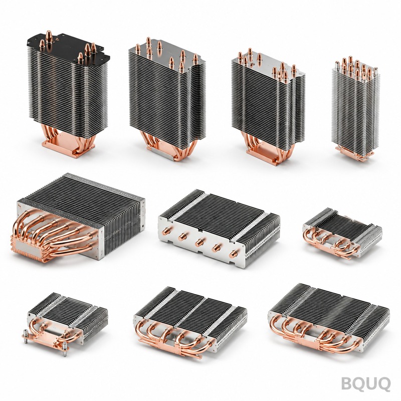
The thermal design of a heat sink for IGBT and power modules is governed by a single non-negotiable requirement: maintaining the junction temperature (Tj) below the manufacturer’s absolute maximum rating, typically 150°C for silicon IGBTs and 175°C for silicon carbide (SiC) devices, while ensuring long-term reliability at lower continuous operating temperatures (usually 125°C or less). This is achieved by managing the total thermal resistance from junction to ambient (RthJA) through precise calculation of the module’s thermal impedance, proper interface material selection, and optimized forced convection or liquid cooling. For a typical 1200V/300A IGBT module dissipating 600W, the total heat sink thermal resistance must be below 0.12°C/W when the ambient temperature is 40°C, which often requires a high-performance extruded aluminum profile with a thermal resistance of 0.05-0.08°C/W at airflow rates of 3-5 m/s.
What Is the Maximum Junction Temperature for IGBT Modules?
The maximum junction temperature for standard silicon IGBTs is 150°C, while newer field-stop trench IGBTs and SiC MOSFETs allow 175°C, but these are absolute limits, not operating recommendations. For continuous operation, design engineers should target a maximum junction temperature of 125°C to prevent thermal fatigue in solder layers and bond wires, which experience coefficient of thermal expansion (CTE) mismatch stress. For example, a 100A/1200V IGBT module (e.g., Infineon FF100R12RT4) has a junction-to-case thermal resistance (RthJC) of approximately 0.12°C/W, meaning at 300W dissipation, the case temperature must not exceed 121°C to keep the junction at 150°C.
How Do You Calculate the Required Heat Sink Thermal Resistance?
The required heat sink thermal resistance (RthSA) is calculated using the formula: RthSA = (Tj_max - Ta) / P - RthJC - RthCS, where Tj_max is the maximum junction temperature, Ta is the ambient temperature, P is the power dissipation, RthJC is the junction-to-case resistance, and RthCS is the case-to-sink resistance from the thermal interface material (TIM). For a practical example, consider a 600W IGBT module with RthJC of 0.08°C/W, a TIM with RthCS of 0.02°C/W, an ambient temperature of 45°C, and a Tj_max of 125°C: RthSA = (125-45)/600 - 0.08 - 0.02 = 0.133 - 0.10 = 0.033°C/W. This is an extremely low value, demanding a large liquid-cooled cold plate or a high-velocity forced-air heat sink with fin density of 8-10 fins per inch and base thickness of 10-12mm.
Which Heat Sink Materials Are Best for High-Power IGBTs?
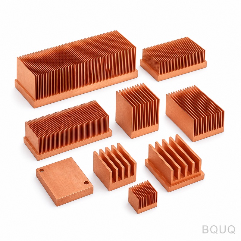
Aluminum 6063-T5 is the industry standard for IGBT heat sinks due to its thermal conductivity of 180-200 W/m·K, low cost (approximately $4-6 per kg in China), and excellent extrusion capability for complex fin geometries. For higher performance, copper heat sinks (thermal conductivity 385-400 W/m·K) are used in space-constrained applications, but they are 3-4 times more expensive and 3.3 times heavier than aluminum, making them impractical for most industrial drives. A hybrid approach uses copper inserts or heat pipes embedded in aluminum bases, reducing thermal resistance by 15-25% while maintaining acceptable weight and cost; for example, a 400mm x 200mm aluminum heat sink with three heat pipes can achieve a thermal resistance of 0.05°C/W versus 0.08°C/W for a solid aluminum profile.
How Does Airflow Velocity Affect Heat Sink Performance?
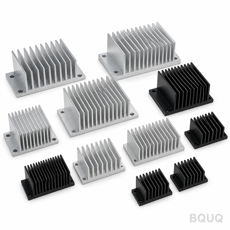
Airflow velocity is the most critical variable in forced convection cooling, with typical industrial fan speeds providing 2-6 m/s across the heat sink face, yielding convective heat transfer coefficients of 30-100 W/m²·K. Increasing airflow from 2 m/s to 4 m/s can reduce thermal resistance by 25-35%, but beyond 6 m/s the gains diminish while acoustic noise increases logarithmically, often exceeding 65 dBA. For a standard 200mm wide aluminum extrusion with 6mm fin pitch and 40mm fin height, the thermal resistance drops from 0.12°C/W at 1 m/s natural convection to 0.06°C/W at 3 m/s, and to 0.04°C/W at 5 m/s, as measured in BQUQ’s wind tunnel testing with a 300W heat source.
What Is the Role of Thermal Interface Material in IGBT Cooling?
The thermal interface material (TIM) bridges the microscopic air gaps between the IGBT baseplate and heat sink, which would otherwise create a thermal resistance of 0.5-1.0°C/W due to air’s low conductivity (0.026 W/m·K). Common TIMs include phase-change materials (0.05-0.10°C·in²/W), thermal greases (0.04-0.08°C·in²/W), and gap pads (0.10-0.20°C·in²/W), with phase-change materials being preferred for IGBTs because they pump out under thermal cycling without drying out. The clamping pressure should be 20-50 psi (1.4-3.5 kg/cm²) for optimal TIM performance; insufficient pressure increases RthCS by 50-100%, while excessive pressure can crack the IGBT substrate or warp the heat sink base.
How Do You Design a Heat Sink for Thermal Cycling and Vibration?
Thermal cycling from 25°C to 125°C induces differential expansion of 0.15-0.25mm per 100mm length between an aluminum heat sink and a copper baseplate, which causes shear stress on solder joints and can lead to delamination after 10,000-20,000 cycles. To mitigate this, design should use a heat sink base thickness of 8-12mm to distribute stress, mount the module with spring clips or Belleville washers that maintain constant pressure, and specify anodized surfaces (hard anodize, 25-50 microns) for corrosion resistance and improved emissivity (0.8-0.9) for radiant cooling. For vibration resistance in traction or marine applications, the heat sink must be rigid with a first natural frequency above 200 Hz; this is achieved by minimizing unsupported length, adding stiffening ribs, or using a liquid-cooled cold plate with a thick (12-15mm) aluminum base.
Which Cooling Method Is More Effective: Forced Air or Liquid Cooling?
Liquid cooling outperforms forced air by a factor of 5-10 in heat removal capability, with liquid cold plates achieving thermal resistances of 0.01-0.03°C/W versus 0.04-0.10°C/W for high-performance air-cooled heat sinks. For power dissipations below 800W, forced air cooling is usually more cost-effective, with a typical heat sink plus fan assembly costing $15-40; above 800W or when ambient temperatures exceed 50°C, liquid cooling becomes necessary to maintain Tj below 125°C. A 600mm x 150mm liquid cold plate with copper tubes or micro-channel structure can handle 2000-5000W at a flow rate of 6-10 L/min with a pressure drop of 0.2-0.5 bar, compared to an air-cooled heat sink of the same size that would require 4-6 fans and still only dissipate 600-800W.
| Heat Sink Type | Thermal Resistance (°C/W) | Max Power (W) | Relative Cost | Typical Application |
| Extruded Aluminum, Natural Convection | 0.20-0.50 | 50-200 | $5-15 | Low-power drives, servo amplifiers |
| Extruded Aluminum, Forced Air (2-4 m/s) | 0.05-0.12 | 200-800 | $15-40 | Industrial inverters, welding machines |
| Skived Fin Copper, Forced Air | 0.03-0.06 | 400-1200 | $50-120 | High-frequency converters, UPS systems |
| Liquid Cold Plate (Aluminum/Copper) | 0.01-0.03 | 800-5000 | $60-200 | Traction drives, wind turbines, EV chargers |
| Heat Pipe Embedded Aluminum | 0.04-0.08 | 300-1000 | $30-80 | Solar inverters, medical equipment |
How Do You Validate a Heat Sink Design Before Production?
Validation begins with computational fluid dynamics (CFD) simulation using software like Ansys Icepak or Flotherm, which predicts junction temperature within 5-10% accuracy when boundary conditions are correctly specified. Prototype testing involves mounting a real IGBT module or a calibrated resistor heater, measuring temperatures with thermocouples at the case, baseplate, and heat sink fins, and recording thermal impedance curves using a thermal transient tester like the Mentor Graphics T3Ster. For production qualification, BQUQ performs 100% leak testing on liquid cold plates at 0.6 MPa pressure and thermal resistance spot checks on air-cooled heat sinks using a standardized test rig with 100W input and 3 m/s airflow, rejecting units exceeding 0.08°C/W for a specified profile.
When Should You Choose a Custom Heat Sink Instead of a Standard Profile?
A custom heat sink is justified when the standard extrusion cannot meet the thermal resistance target, when mounting hole patterns for the IGBT module do not align with standard profiles, or when space constraints in the enclosure require non-standard fin directions or base thickness. Custom extrusions require a tooling investment of $1,500-4,000 in China, with a minimum order of 500-1000 kg, and lead time of 3-4 weeks for tooling plus 1-2 weeks for production; this is economical if the annual volume exceeds 2,000 units. Alternatively, a standard profile with secondary machining (drilling, tapping, milling) can be delivered in 5-7 days with no tooling cost, making it the preferred choice for prototypes and low-volume production where the thermal resistance requirement is not extremely stringent.
FAQ
What Is the Typical Heat Sink Size for a 100A IGBT Module?
A 100A/1200V IGBT module dissipating approximately 200-300W typically requires a heat sink of 200mm x 150mm x 40mm (width x depth x fin height) with forced air cooling at 3 m/s, achieving a thermal resistance of about 0.10°C/W. With natural convection, the size must increase to 300mm x 200mm x 60mm to achieve the same thermal performance, which is why most industrial designs use at least a small fan.
Can I Use the Same Heat Sink for Different IGBT Modules?
Yes, but only if the thermal resistance of the heat sink is lower than the worst-case requirement among all modules, which means designing for the highest power dissipation module. You must also ensure the mounting hole pattern is compatible or use a universal baseplate adapter plate, which adds 0.01-0.02°C/W thermal resistance due to the extra interface.
How Often Should Thermal Interface Material Be Replaced?
Phase-change materials and thermal greases should be replaced whenever the IGBT module is removed from the heat sink, as the material degrades and picks up contaminants during disassembly. In continuous operation without module removal, the TIM can last the lifetime of the product (10-15 years), but if thermal resistance increases by more than 20% as detected by temperature monitoring, the TIM should be renewed.
What Is the Effect of Altitude on Heat Sink Performance?
At altitudes above 1,000 meters, air density decreases, reducing the convective heat transfer coefficient by approximately 1% per 100 meters, so a heat sink designed at sea level will run 5-10% hotter at 2,000 meters altitude. For high-altitude applications such as mining equipment or mountain wind turbines, increase the heat sink size by 10-15% or increase fan speed to compensate.
Are Black Anodized Heat Sinks Always Better Than Bare Aluminum?
Black anodizing (emissivity 0.85-0.95) is significantly better than bare aluminum (emissivity 0.05-0.10) for natural convection cooling, where radiation accounts for 30-50% of total heat transfer. However, under forced convection with airflow above 2 m/s, the convective component dominates and the anodizing provides only a 3-5% improvement, while adding 10-15% to the cost and slightly reducing thermal conductivity through the coating layer.
What Is the Maximum Heat Flux an Aluminum Heat Sink Can Handle?
An aluminum heat sink with forced air cooling can handle a maximum heat flux of 5-10 W/cm² at the baseplate, while a liquid-cooled cold plate can handle 50-100 W/cm² without exceeding a 40°C temperature rise. For heat fluxes above 100 W/cm², such as in some advanced SiC modules, direct liquid jet impingement or micro-channel cooling is required, which can achieve 500-1,000 W/cm².
How Do I Measure the Actual Thermal Resistance of My Heat Sink?
Measure the temperature difference between the heat sink base and ambient using thermocouples while dissipating a known power through a resistor heater, then divide the temperature difference by the power to obtain RthSA in °C/W. Ensure the test is performed in a controlled environment with no external drafts, and allow at least 30 minutes for thermal equilibrium before recording data.
At BQUQ, we have 20 years of experience manufacturing precision heat sinks for IGBT and power module applications, using CNC machining, metal stamping, and custom extrusion processes to achieve tolerances of ±0.05mm and thermal resistance values verified by in-house testing. Our engineering team provides free thermal simulation and design recommendations based on your module specifications, power dissipation, and environmental conditions. For a quotation within 12 hours, contact us at sc@bquq.com or WhatsApp +86 13713157787, and visit www.bquq.com for our catalog of standard profiles and custom cooling solutions.
Related Articles
- How to Attach a Heat Sink Without Screws: Thermal Adhesive Guide
- New energy vehicle IGBT heat dissipation, heat sink reliability engineering, heat pipe and temperature plate integrated heat sink, surface treatment and heat radiation enhancement: anodic oxidation, black coating and micro-nano structure, graphene/3D printing/intelligent thermal management: 2030 heat sink technology roadmap
- Hardware heat sink reconstruction under liquid-cooled penetration of AI server: cold plate, microchannel and two-phase flow


