
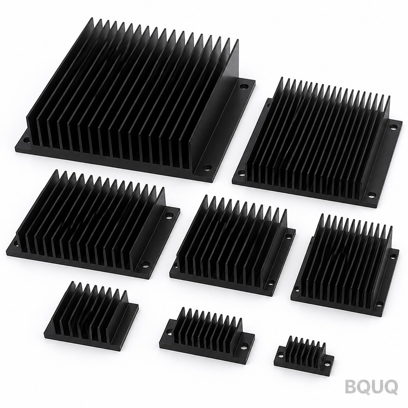
What Is the Minimum Extruded Heat Sink Fin Thickness?
The minimum practical fin thickness for aluminum extruded heat sinks is 0.8 mm (0.031 inches) for standard production, with 0.6 mm (0.024 inches) achievable only under specific conditions using high-pressure extrusion with specialized alloys. For most thermal management applications, a fin thickness between 1.0 mm and 1.5 mm offers the best balance of manufacturability, tooling life, and thermal performance. Below 0.8 mm, the extrusion pressure increases exponentially, tooling wear accelerates, and the aspect ratio (fin height to thickness) becomes the dominant limiting factor.
What Is the Theoretical Minimum Fin Thickness for Aluminum Extrusion?
The theoretical minimum is governed by the extrusion ratio and the flow stress of the aluminum alloy. For 6063-T5 alloy, the most common heat sink material, the absolute lower limit is approximately 0.5 mm (0.020 inches) when using a 2500-ton extrusion press with a billet temperature of 480°C. However, this is not commercially viable because die deflection causes fin tip tearing and inconsistent thickness across the extrusion length. In practice, BQUQ's 20 years of extrusion experience shows that 0.8 mm is the repeatable minimum for lengths over 300 mm, while 0.6 mm can be held only for fin heights under 15 mm and lengths under 150 mm.
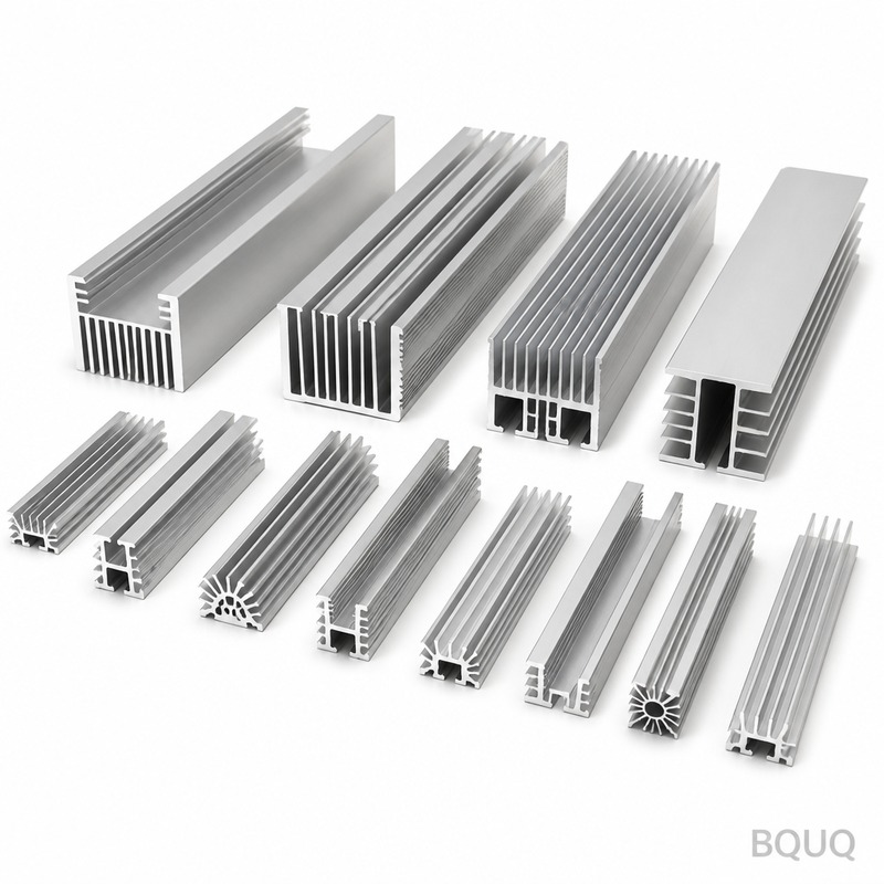
How Does Fin Height Affect the Minimum Thickness?
The fin height-to-thickness aspect ratio is the critical geometric constraint. For a given extrusion press, the maximum aspect ratio for 6063 alloy is 20:1 with a conventional die, extending to 25:1 with a porthole die. This means a 1.0 mm fin can be extruded to a maximum height of 20 mm. If you need a 30 mm fin height, the minimum thickness rises to 1.5 mm. Exceeding these ratios causes the aluminum to flow unevenly, producing wavy fins and dimensional deviation exceeding ±0.1 mm. The table below summarizes achievable fin geometries based on our production data.
| Fin Thickness (mm) | Max Fin Height (mm) | Max Extrusion Length (mm) | Typical Tolerance (mm) | Relative Tooling Cost |
| 0.6 | 12 | 150 | ±0.08 | 2.2x |
| 0.8 | 16 | 300 | ±0.10 | 1.5x |
| 1.0 | 20 | 600 | ±0.10 | 1.2x |
| 1.2 | 24 | 1200 | ±0.12 | 1.0x |
| 1.5 | 30 | 2000 | ±0.15 | 0.9x |
| 2.0 | 40 | 3000 | ±0.18 | 0.8x |
Which Aluminum Alloy Allows the Thinnest Fins?
The alloy choice directly determines the minimum achievable thickness because higher silicon and magnesium content improves flowability. 6063-T5, with 0.45% magnesium and 0.35% silicon, is the standard for thin fins because it offers the lowest flow stress among extrusion alloys. 6061-T6, while stronger, has higher flow stress and requires a minimum thickness of 1.2 mm to avoid surface tearing. The 6005A alloy, containing 0.6% magnesium, can achieve 0.7 mm fins but at a 15% slower extrusion speed. For production economics, 6063 remains the only alloy that supports sub-1.0 mm fins without requiring a 3000-ton press or specialized lubrication systems.
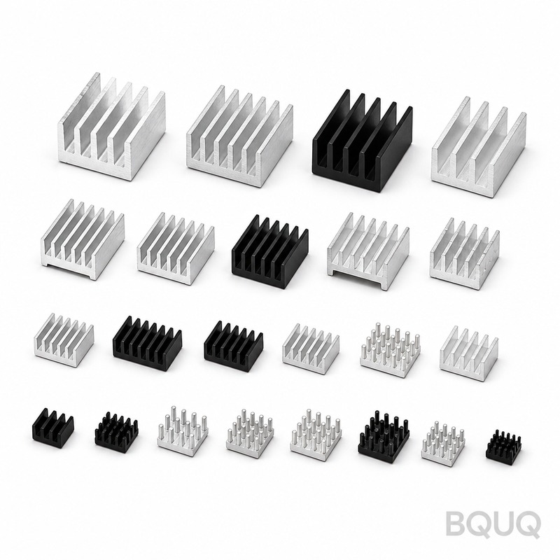
How Much Does Tooling Cost for Thin Fin Extrusion?
Tooling cost escalates sharply as fin thickness drops below 1.0 mm because the die must be manufactured from H13 tool steel with EDM-machined slots. For a 200 mm x 200 mm die with 20 fins, the cost structure is as follows: a 1.5 mm fin die costs USD 1,800 to 2,200; a 1.0 mm fin die costs USD 2,500 to 3,000; a 0.8 mm fin die costs USD 3,800 to 4,500 due to the need for vacuum heat treatment and nitriding; and a 0.6 mm fin die costs USD 6,000 to 8,000 because it requires a multi-piece construction with removable inserts. Die life also decreases from 50,000 kg of extruded aluminum at 1.5 mm to only 12,000 kg at 0.6 mm, meaning your per-kilogram tooling amortization increases by a factor of 4.5.
Why Does Extrusion Speed Decrease With Thinner Fins?
Thinner fins require slower ram speeds to prevent the aluminum from cooling prematurely in the die channels. At 1.5 mm fin thickness, an 1800-ton press can run at 25 meters per minute exit speed. At 1.0 mm, the speed drops to 18 meters per minute. At 0.8 mm, it falls to 12 meters per minute, and at 0.6 mm, only 7 meters per minute is safe. This reduction occurs because the surface-to-volume ratio of the fin channel increases, causing heat loss to the die steel at a rate of 8-10°C per second. If the billet temperature drops below 430°C at the die exit, the aluminum becomes too stiff, leading to die blockage or torn fins. The slower speed increases production cost by approximately 35% for every 0.2 mm reduction in thickness.
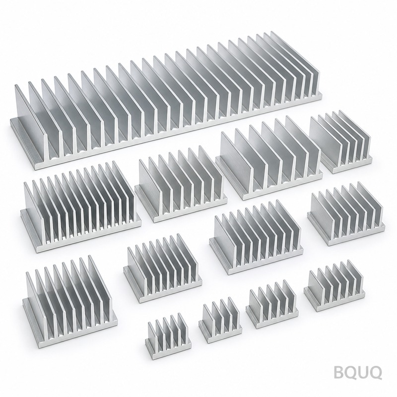
What Thermal Performance Trade-Offs Exist at Thin Fin Thickness?
A thinner fin improves thermal performance by increasing the number of fins per unit width, but only to a point. For a natural convection heat sink, reducing fin thickness from 2.0 mm to 1.0 mm at a fixed pitch of 6 mm increases the fin count by 20%, improving thermal resistance by 12-15% (from 0.85°C/W to 0.73°C/W for a 100 mm x 100 mm base). However, going from 1.0 mm to 0.8 mm yields only a 4% improvement because the boundary layer thickness of still air (about 2 mm) begins to dominate. Under forced convection with 3 m/s airflow, the improvement from 1.0 mm to 0.8 mm is even smaller at 2%. The structural fragility of 0.6 mm fins also requires a 30% derating factor for vibration loads, making them unsuitable for automotive or fan-cooled applications.
When Should You Choose Skived or Bonded Fins Instead of Extruded?
Skived fins (machined from solid copper or aluminum) should be chosen when you need fin thickness below 0.5 mm, which extrusion cannot reliably produce. Skiving achieves 0.3 mm fins with a height of 25 mm, delivering a 40% higher surface area than the thinnest extruded profile. Bonded fins (epoxy or brazed) are preferred when you need mixed materials, such as copper fins on aluminum bases, or when fin height exceeds 50 mm. However, skiving costs USD 0.30-0.50 per fin per 100 mm length versus USD 0.08-0.12 for extrusion, so the decision hinges on whether the thermal gain justifies a 3-4x cost premium. For production volumes above 5,000 units per year, extrusion at 0.8 mm remains the most economical option.
What Is the Cost Difference Between 1.5 mm and 0.8 mm Extruded Fins?
The price per kilogram for extruded heat sinks increases by 25-40% when fin thickness drops from 1.5 mm to 0.8 mm. At current aluminum prices (USD 2,400 per ton for 6063 billet), a 200 mm x 100 mm x 25 mm heat sink with 1.5 mm fins weighs 0.85 kg and costs USD 2.04 in material plus USD 1.50 in extrusion and anodizing. The same size with 0.8 mm fins weighs 0.62 kg (27% lighter) but costs USD 1.49 for material, USD 2.30 for extrusion (due to slower speed), and USD 1.80 for tooling amortization at 10,000 units, totaling USD 5.59 versus USD 3.54 for the 1.5 mm version. The thinner fin is 58% more expensive per unit, but it delivers a 15% lower thermal resistance, which may justify the cost in LED lighting or IGBT cooling where every degree Celsius matters.
FAQ
Can 0.5 mm fins be extruded at all?
Yes, 0.5 mm fins can be extruded in a laboratory setting using a 4000-ton press with 7075 alloy and isothermal extrusion at 500°C. However, production yields are below 60% due to fin bending and thickness variation, making the effective cost per good part 5-8 times higher than a 1.0 mm design. BQUQ does not recommend 0.5 mm for any production application.
What is the standard fin thickness range for most commercial heat sinks?
The industry standard is 1.2 mm to 2.0 mm, with 1.5 mm being the most common for natural convection and 1.2 mm for forced convection. This range offers the best combination of die life, extrusion speed, and structural rigidity while maintaining 85-90% of the thermal performance of thinner fins.
How does anodizing affect thin fin dimensions?
Anodizing adds 0.005 mm to 0.010 mm per surface, which means a 0.8 mm fin becomes 0.81-0.82 mm after coating. For fins under 1.0 mm, this can cause the gap between fins to close by 2-3%, potentially reducing airflow. BQUQ recommends specifying anodizing thickness of 8-10 microns (0.008-0.010 mm) maximum for fins below 1.0 mm.
Which industries commonly use sub-1.0 mm extruded fins?
LED lighting modules and compact power supplies are the primary users of 0.8-1.0 mm fins because their heat dissipation requirements are modest (5-15 W) and space constraints are severe. Telecommunications equipment with 19-inch rack enclosures also uses 0.9 mm fins to maximize fin count within a 40 mm height limit.
What is the lead time for thin fin extrusion tooling?
Standard 1.5 mm fin tooling takes 3-4 weeks, while 0.8 mm tooling requires 5-6 weeks due to additional EDM machining and heat treatment steps. Prototype 0.6 mm dies can take up to 8 weeks because they require iterative testing and die corrections after the first extrusion trial.
Can thin fins be straightened after extrusion?
Yes, but only up to a point. Fins thinner than 1.0 mm can be mechanically straightened using a roller leveler, but this adds USD 0.05 per fin and introduces residual stress that may cause thermal warping above 80°C. For 0.6 mm fins, straightening is not recommended because the yield strength is too low to maintain flatness.
Conclusion
For 95% of engineering applications, the optimal extruded fin thickness is 1.0 mm to 1.5 mm, with 0.8 mm reserved for space-constrained designs that can tolerate a 25-40% cost increase. Do not specify 0.6 mm fins unless you have a documented thermal requirement that cannot be met by any other geometry, and always verify the aspect ratio against your required fin height. When in doubt, request a thermal simulation from BQUQ with your actual airflow and power figures—we will recommend the thinnest practical fin that meets your temperature target without breaking your budget.
At BQUQ, our extrusion engineers provide free design-for-manufacturing reviews and thermal modeling within 12 hours of receiving your CAD file. Contact us at sc@bquq.com or WhatsApp +86 13713157787, or visit www.bquq.com to upload your design and receive a firm quote with tooling costs and lead times.


