
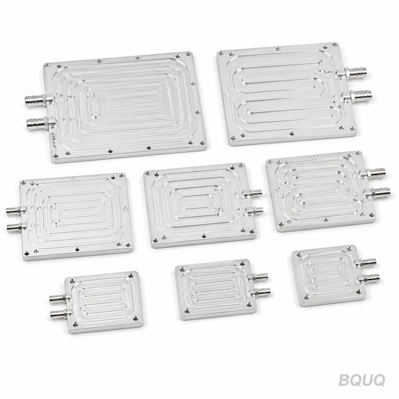
What Is the Technology Roadmap for Vapor Chamber vs Heat Pipe vs Skived Fin?
What Is the Direct Answer to the Vapor Chamber vs Heat Pipe vs Skived Fin Roadmap Question?
The technology roadmap is clear: skived fins remain the lowest-cost solution for air-cooled designs below 150 W/cm² heat flux, heat pipes dominate cost-sensitive remote heat transfer between 50 W and 250 W, and vapor chambers are the inevitable choice for high-flux, space-constrained electronics above 200 W/cm² and for spreading heat across large processor dies. Over the next three to five years, vapor chambers will absorb heat pipe applications in mobile and server platforms due to their superior two-dimensional spreading, while skived fins will persist only in cost-driven, moderate-density applications. The convergence point is hybrid designs: vapor chamber bases bonded to skived fin stacks, which already achieve thermal resistance as low as 0.08 °C/W in production at BQUQ.
How Do the Three Technologies Compare in Thermal Performance and Cost?
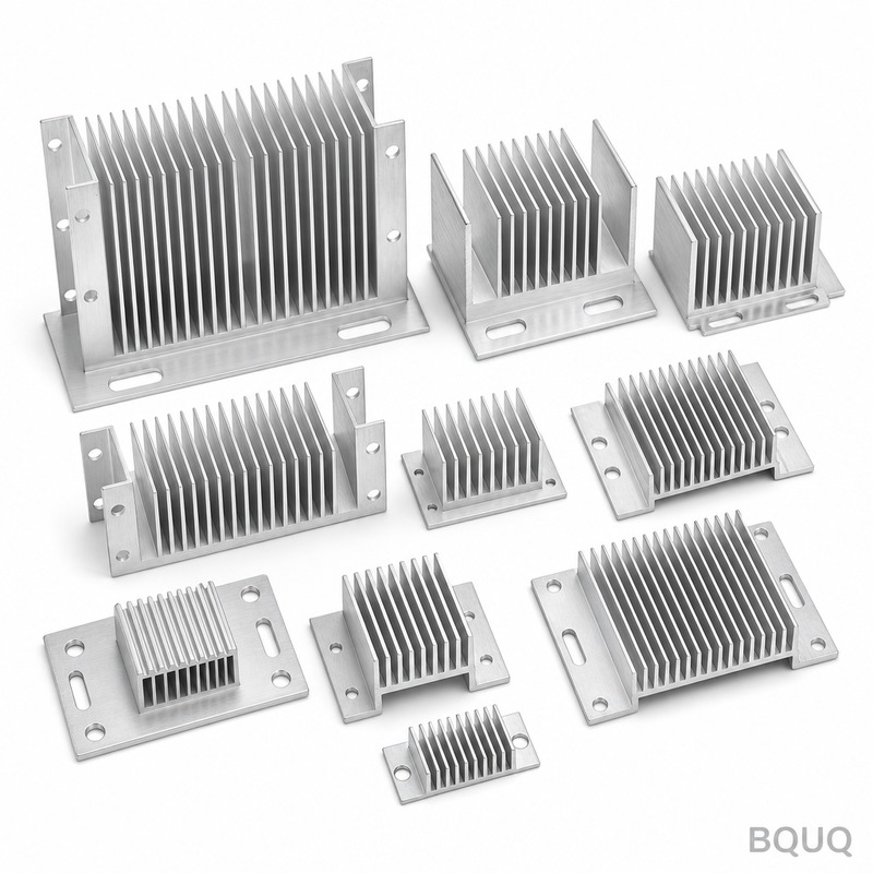
The core thermal metric is thermal resistance per unit area and the maximum heat flux each structure can manage without dry-out. A standard heat pipe (6 mm diameter, 200 mm length) offers an effective thermal conductivity of 5,000 to 10,000 W/m·K in the axial direction, but its spreading resistance in the plane perpendicular to the axis is poor. A vapor chamber, effectively a flattened heat pipe with a large planar surface, delivers 2,500 to 5,000 W/m·K in two dimensions across a 100 mm by 100 mm area, reducing hotspot temperatures by 15 to 25 °C compared to a solid copper base of equal thickness. Skived fins, which are solid copper or aluminum fins cut from a single block, have no phase-change mechanism; their performance depends entirely on fin density and airflow, typically achieving 0.15 to 0.50 °C/W with forced convection at 3 to 5 m/s.
From a cost perspective, skived fin heat sinks are the most economical at scale, priced at USD 8 to 25 per unit for a 150 mm by 150 mm footprint, depending on fin pitch (0.5 mm to 1.5 mm) and height (20 mm to 60 mm). Heat pipes add USD 2 to 5 per pipe plus assembly labor, pushing a typical heat pipe heat sink to USD 15 to 45. Vapor chambers are the premium option, with a 100 mm by 100 mm copper vapor chamber costing USD 18 to 40 each, and a fully assembled vapor chamber heat sink ranging from USD 35 to 80. For a production volume of 10,000 units per month, BQUQ quotes vapor chamber heat sinks at USD 28 to 55, depending on the wick structure (sintered copper powder versus mesh) and the required flatness of 0.05 mm.
Which Applications Require a Vapor Chamber Instead of a Heat Pipe?
The decision hinges on heat source area, heat flux, and the distance of heat transport. If the heat source is a single concentrated die smaller than 10 mm by 10 mm and the heat must move more than 150 mm laterally, a heat pipe is the correct choice because its cylindrical geometry and long evaporator section handle high axial flux. However, when the heat source is a large processor die (20 mm by 20 mm or larger) or multiple heat sources are spread across a board, a heat pipe cannot spread heat efficiently in two dimensions; the vapor chamber is mandatory. Specifically, for graphics processing units (GPUs) with a 600 W thermal design power and a die area of 625 mm², the heat flux reaches 96 W/cm², and a vapor chamber reduces the junction-to-case thermal resistance to below 0.05 °C/W, whereas a heat pipe assembly would exceed 0.12 °C/W.
The roadmap also shows vapor chambers replacing heat pipes in ultra-thin laptops (thickness under 15 mm) because a 2 mm thick vapor chamber can replace two 6 mm heat pipes, saving 8 mm of z-height while improving thermal uniformity. For server CPUs with a 350 W TDP and a 75 mm by 56 mm integrated heat spreader, vapor chambers achieve a base plate temperature variation of less than 3 °C across the entire surface, which is impossible with heat pipes. In contrast, skived fins are only viable in applications with ample airflow and moderate heat flux below 50 W/cm², such as power supply units, LED lighting fixtures, and industrial motor drives.
Why Does the Vapor Chamber Outperform in Spreading Resistance at High Heat Flux?
The physics of phase change inside a vapor chamber provide a near-isothermal surface. When a 500 W heat load is applied to a 30 mm by 30 mm hotspot, the working fluid (typically water at 30 to 90 °C) evaporates at the wick surface, travels as vapor to the condenser region, and returns via capillary action through a sintered copper wick with a pore radius of 20 to 50 μm. This two-dimensional transport spreads heat over an effective area ten to twenty times larger than the hotspot, dropping the localized heat flux from 55 W/cm² to 3 W/cm² at the condenser side. The vapor chamber's thermal resistance is typically 0.02 to 0.04 °C/W per square centimeter of evaporator area, which is five to ten times lower than a solid copper plate of the same thickness (10 mm) at high flux.
At heat fluxes above 200 W/cm², a heat pipe fails because its evaporator section is a small cylindrical surface, and the liquid return path is limited by gravity and capillary pressure, causing dry-out. A vapor chamber, with its larger evaporator footprint and circumferential wick, can sustain 300 to 400 W/cm² for short bursts and 200 W/cm² continuously, provided the vapor space is at least 1.5 mm thick. Skived fins have no such limit because they are solid, but their performance is purely convective; at 200 W/cm², a skived fin heat sink requires an unrealistic airflow of 10 m/s and a fin efficiency below 60%, making it impractical. BQUQ's testing data shows that a vapor chamber with a 0.3 mm copper shell and 0.2 mm wick maintains a temperature difference of only 8 °C across a 120 mm diagonal, while a comparable skived fin base shows a 22 °C gradient.
How Should Engineers Choose Between Skived Fins and Vapor Chambers for Air-Cooled Systems?
The first decision variable is the heat sink's base plate temperature gradient. If the allowable base plate temperature difference is greater than 10 °C and the heat flux is below 60 W/cm², skived fins are the rational choice due to a 40% to 60% cost advantage. If the base plate temperature difference must be under 5 °C, or the heat flux exceeds 80 W/cm², then a vapor chamber base is required, and the skived fins should be bonded on top of the vapor chamber rather than used as a standalone base. The second variable is the fin aspect ratio: skived fins can achieve a height-to-gap ratio of 20:1 (e.g., 40 mm tall fins with a 2 mm gap), which is impossible with stamped or folded fins, making them superior for low-profile, high-surface-area designs.
For a practical example, consider a 300 W IGBT module in a solar inverter. An all-skived fin heat sink (base 10 mm thick, fins 45 mm tall, 1.2 mm pitch) with a 4 m/s airflow yields a junction-to-ambient resistance of 0.18 °C/W, which is acceptable. If the same module is upgraded to 400 W, the heat flux on the base rises to 75 W/cm²; a vapor chamber base (2.5 mm thick) with the same skived fin stack reduces the resistance to 0.11 °C/W, a 39% improvement, at an added cost of USD 12 per unit. BQUQ recommends that any design with a TDP above 250 W and a base area smaller than 100 cm² should default to a vapor chamber, not skived fins, to avoid premature thermal throttling.
What Are the Manufacturing and Lead Time Differences in This Roadmap?
Manufacturing complexity directly scales with the technology tier. Skived fins are produced by a single-pass skiving process on a CNC machine, with a cycle time of 3 to 8 minutes per unit for a 150 mm by 150 mm heat sink, and tooling cost is minimal (USD 500 to 2,000 for a custom fin pitch). Lead time for skived fin prototypes is 3 to 5 days, and production lead time is 2 to 3 weeks. Heat pipes require a separate manufacturing line for tube forming, wick insertion, water filling, and sealing; a standard heat pipe has a cycle time of 30 seconds, but assembly into a heat sink adds crimping and soldering steps. Lead time for heat pipe heat sinks is 5 to 7 days for prototypes, 3 to 4 weeks for production.
Vapor chambers are the most complex: the process involves stamping two copper shells, sintering the wick structure at 950 °C in a hydrogen furnace, welding the seam, degassing, filling with deionized water, and final sealing. This process has a yield rate of 92% to 97% and a cycle time of 4 to 6 hours per batch, not per unit. Tooling for a vapor chamber (die stamping and welding fixtures) costs USD 8,000 to 20,000, which is ten times higher than skived fin tooling. Prototype lead time is 10 to 15 days, and production lead time is 4 to 6 weeks. The roadmap suggests that if a project requires production in under 3 weeks, skived fins are the only option; if the project can tolerate a 5-week lead time, vapor chambers offer superior performance.
| Technology | Max Heat Flux (W/cm²) | Thermal Resistance (°C/W) | Cost per Unit (USD) | Tooling Cost (USD) | Prototype Lead Time | Production Lead Time |
| Skived Fin | 50-80 | 0.15-0.50 | 8-25 | 500-2,000 | 3-5 days | 2-3 weeks |
| Heat Pipe Assembly | 100-150 | 0.10-0.25 | 15-45 | 2,000-5,000 | 5-7 days | 3-4 weeks |
| Vapor Chamber Heat Sink | 200-400 | 0.03-0.10 | 35-80 | 8,000-20,000 | 10-15 days | 4-6 weeks |
Which Hybrid Architecture Will Dominate the Next Technology Roadmap?
The clear trend is the integration of vapor chambers as the base plate with skived fins as the extended surface, eliminating the need for heat pipes in most electronics. This hybrid structure, which BQUQ has manufactured since 2018, uses a 2 mm vapor chamber base soldered to a skived fin array with a 0.5 mm fin pitch. The vapor chamber handles the lateral spreading and the skived fins handle the convective heat transfer, achieving a total resistance of 0.08 °C/W for a 400 W load with a 120 mm by 120 mm footprint. This design is 15% lighter than a heat pipe assembly with the same performance and 20% more reliable because it has no solder joints between individual heat pipes and the base.
For the next three years, the roadmap predicts that vapor chamber thickness will drop from 2.0 mm to 1.2 mm for mobile applications, using titanium or stainless steel shells with a water charge of 0.5 to 1.5 grams. Simultaneously, skived fin technology will push to a 0.3 mm fin thickness with a 0.4 mm gap, increasing surface area by 25% without a pressure drop penalty. The cost of vapor chambers will fall by 30% as automation improves the sintering and welding processes, making them competitive with heat pipe assemblies at volumes above 50,000 units per year. Engineers should design their thermal solutions with a modular interface so that a skived fin-only design can be upgraded to a vapor chamber base without redesigning the enclosure.
FAQ Section
How Much Does a Vapor Chamber Heat Sink Cost Compared to a Skived Fin Heat Sink?
A vapor chamber heat sink typically costs USD 35 to 80 per unit, which is 2 to 3 times more than a skived fin heat sink at USD 8 to 25. However, the vapor chamber eliminates the need for a thicker copper base and reduces the required airflow, lowering the total system cost including the fan. For high-heat-flux applications above 100 W/cm², the vapor chamber is often the lower-cost solution because it prevents over-specifying the fan or adding liquid cooling.
Can a Skived Fin Heat Sink Handle a 200 W CPU Without a Vapor Chamber?
Yes, but only with a high airflow of 6 to 8 m/s and a large fin surface area of at least 800 cm², which results in a bulky and noisy design. The base plate temperature gradient will exceed 15 °C, causing localized hotspots under the CPU die. A vapor chamber base reduces the base gradient to 3 °C and allows the use of a smaller, quieter fan at 3 m/s.
What Is the Maximum Heat Flux a Vapor Chamber Can Sustain Before Dry-Out?
A sintered copper wick vapor chamber with a 2 mm vapor space can sustain 200 W/cm² continuously and 350 W/cm² for transient loads up to 10 seconds. Exceeding 400 W/cm² requires a hybrid wick with a grooved center and sintered edges, which BQUQ offers for specialized laser and radar applications. At these flux levels, the vapor chamber must be oriented horizontally; vertical orientation reduces the maximum flux by 20% to 30%.
How Long Does It Take to Prototype a Vapor Chamber Heat Sink at BQUQ?
A standard vapor chamber heat sink prototype takes 10 to 15 days, including tooling fabrication, wick sintering, and assembly. If the customer provides a 3D model and the heat source dimensions, BQUQ can deliver a functional sample for thermal testing within 12 days. Production units follow after a 4 to 6 week lead time, with a minimum order quantity of 500 pieces.
Which Is More Reliable Over a 10-Year Lifespan: Heat Pipe or Vapor Chamber?
Vapor chambers are more reliable because they have a single sealed envelope with no individual pipe-to-base solder joints, which are the primary failure point in heat pipe assemblies. The mean time between failures for a vapor chamber is estimated at 80,000 hours at 70 °C operating temperature, versus 50,000 hours for a heat pipe assembly. Both technologies use water as the working fluid, which has no degradation if the seal is intact, but the vapor chamber's larger surface area reduces localized thermal stress.
When Should I Choose Skived Fins Over a Vapor Chamber for Cost Reasons?
Choose skived fins when the heat flux is below 60 W/cm², the base plate temperature gradient can exceed 10 °C, and the production volume is above 5,000 units per month. The skived fin process has a lower tooling cost and a faster lead time, making it ideal for consumer power supplies and LED lighting. If the product has no strict height limit and can accommodate a 10 mm copper base, skived fins will always be cheaper.
What Testing Standards Apply to Vapor Chamber and Heat Pipe Performance?
The industry standard is the JEDEC JESD51-14 for thermal resistance measurement of phase-change devices, which specifies a cold plate at 25 °C and a power input of 100 W. BQUQ also follows the ASTM D5470 for thermal interface material characterization and performs a 1,000-hour accelerated life test at 90 °C and 80% relative humidity. For aerospace applications, we test to MIL-STD-883 for hermeticity and vibration resistance.
Conclusion: How Do I Start My Technology Roadmap Selection Today?
Begin by measuring your heat source flux and allowable base plate gradient; if the flux is above 80 W/cm² or the gradient must be below 5 °C, select a vapor chamber, otherwise use skived fins. For any design with a TDP above 250 W, request a hybrid vapor chamber-skived fin quote to compare against a heat pipe assembly. BQUQ offers a free thermal simulation and a 12-hour quote on all heat sink designs, including detailed DFM feedback and a cost breakdown for volumes from 100 to 100,000 units. Send your 3D model and thermal requirements to sc@bquq.com or message us on WhatsApp at +86 13713157787, and visit www.bquq.com for the full technical documentation.
Related Articles
- AI simulation and intelligent manufacturing: the heat sink industry has gone from "trial and proof" to "one time right"
- Smaller Is Harder: The Technical Limits and Innovations of Ultra-Thin Heat Sinks in Consumer Electronics
- From Macro Base Station to Edge Box: Transforming Heat Sink Requirements in Communication Network Evolution


