
What Is Thermal Resistance in Heat Sinks and How Do You Read the Specs?
Thermal resistance, measured in °C/W, quantifies a heat sink's ability to transfer heat from a component to the ambient air; a lower value indicates better performance. To read the spec, you must match the thermal resistance value against your power dissipation and maximum allowable junction temperature to calculate the required air flow. For a 50W CPU dissipating heat with a 40°C ambient, a heat sink with 1.0 °C/W resistance yields a case temperature of 90°C, which is safe for most silicon junctions.
What Exactly Does Thermal Resistance (°C/W) Mean in a Heat Sink?
Thermal resistance (Rth) is the temperature difference across a heat sink divided by the heat power flowing through it, expressed in degrees Celsius per watt (°C/W). For example, if a 20W load causes a 40°C rise above ambient, the thermal resistance is 2.0 °C/W. This figure combines three resistances in series: the spreading resistance from the component to the baseplate, the conduction resistance through the base, and the convective resistance from the fins to the air. In practical engineering, you use the simplified formula Tj = Ta + (Rth * P), where Tj is junction temperature, Ta is ambient temperature, and P is dissipated power. A 100W IGBT with a 0.5 °C/W heat sink will run at 90°C in a 40°C room, which is acceptable for most industrial modules rated to 125°C.
How Do You Calculate Required Thermal Resistance for Your Application?
You calculate the maximum allowable thermal resistance by dividing the temperature budget by the dissipated power. First, determine the maximum junction temperature (Tj,max) from the component datasheet, typically 125°C for silicon, 150°C for SiC, and 175°C for GaN. Subtract the worst-case ambient temperature (often 40°C for indoor, 60°C for sealed enclosures) to get the allowable temperature rise. Then subtract the thermal resistance of the interface material (typically 0.1 to 0.5 °C/W for thermal paste or phase-change pads). For a 150W power module with Tj,max of 125°C and ambient of 40°C, the budget is 85°C; after subtracting 0.3 °C/W interface resistance, the heat sink must have Rth below (85 / 150) - 0.3 = 0.27 °C/W. This calculation determines whether you need a passive extruded heat sink (0.3-1.0 °C/W) or a forced-air unit with fans (0.05-0.2 °C/W).
Which Factors Most Strongly Influence a Heat Sink's Thermal Resistance?
The dominant factors are fin surface area, air flow rate, and baseplate thickness, in that order. Increasing fin height from 20mm to 40mm can reduce thermal resistance by 30-40% because convective heat transfer scales linearly with surface area. Air velocity is critical: natural convection yields heat transfer coefficients of 5-15 W/m²K, while forced air at 3 m/s raises this to 30-100 W/m²K, cutting thermal resistance by half. Baseplate thickness matters for heat spreading: a 6mm aluminum base distributes heat better than a 3mm base for a concentrated heat source, reducing spreading resistance by up to 20%. Material choice is secondary but significant: copper (385 W/mK) outperforms aluminum (180 W/mK) by about half the conduction resistance, but copper is 3.3 times denser and costs 4-5 times more per volume.
How Do You Read the Thermal Resistance Versus Airflow Curve on a Datasheet?
The spec sheet typically shows a graph with airflow (LFM or m³/min) on the x-axis and thermal resistance (°C/W) on the y-axis, with multiple curves for different heat sink lengths. You must locate the curve for your exact heat sink size, then find the intersection at your desired airflow. For example, a standard 100mm x 100mm x 25mm extruded heat sink may show 1.2 °C/W at 0 LFM (natural convection) dropping to 0.35 °C/W at 400 LFM. Always read the footnote: curves are usually measured with a uniform heat source covering the entire base, not a point source, so real-world values are 10-20% higher for discrete components. If only one number is given without airflow, it is almost always at natural convection (0 LFM) and will be misleading for fan-cooled designs.
Why Is the Interface Material Thermal Resistance Part of the Total Spec?
The interface material between the component and the heat sink base is often the largest single thermal bottleneck in the assembly. A bare aluminum-to-silicon contact has a resistance of 1-5 °C/W due to air gaps filling 90% of the surface; applying thermal grease reduces this to 0.1-0.3 °C/W. For high-power applications, using a 0.25mm thermal pad with 3 W/mK conductivity yields about 0.5 °C/W, while a 0.05mm layer of phase-change material can achieve 0.1 °C/W. The total system resistance is the sum of the heat sink Rth and the interface Rth, so a 0.2 °C/W heat sink with a 0.4 °C/W interface performs worse than a 0.3 °C/W heat sink with a 0.1 °C/W interface. Always specify the interface material in your thermal budget, not just the bare heat sink spec.
What Are Typical Thermal Resistance Values for Different Heat Sink Types?
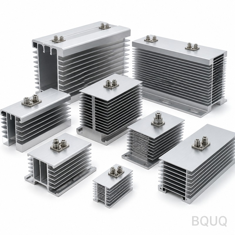
Typical values range from 2.0 °C/W for small natural convection stampings to 0.02 °C/W for large liquid-cooled cold plates. A standard extruded aluminum heat sink (50mm x 50mm x 20mm) in free air has roughly 2.0-3.0 °C/W, while the same part with a 60mm fan drops to 0.8-1.2 °C/W. Larger passive units (150mm x 150mm x 50mm) achieve 0.4-0.7 °C/W in natural convection. Skived copper heat sinks with dense fins (0.2mm pitch) reach 0.1-0.3 °C/W with forced air but cost 3-5 times more than extrusions. For high-density applications, vapor chambers and heat pipes embedded in the base can reduce spreading resistance by 40% but add 20-30% to the price.
| Heat Sink Type | Size (mm) | Thermal Resistance (°C/W) | Airflow Condition | Typical Cost (USD) |
| Extruded aluminum, small | 50 x 50 x 20 | 2.0 - 3.0 | Natural convection | 1.5 - 3.0 |
| Extruded aluminum, medium | 100 x 100 x 25 | 1.0 - 1.5 | Natural convection | 4.0 - 7.0 |
| Extruded aluminum with fan | 100 x 100 x 25 | 0.3 - 0.6 | 400 LFM forced air | 8.0 - 15.0 |
| Stamped aluminum (sheet metal) | 80 x 80 x 15 | 2.5 - 4.0 | Natural convection | 0.8 - 1.5 |
| Skived copper, dense fins | 120 x 120 x 40 | 0.1 - 0.3 | 600 LFM forced air | 25.0 - 45.0 |
| Liquid cold plate (copper) | 100 x 100 x 15 | 0.02 - 0.05 | 2 L/min water | 50.0 - 90.0 |
How Should You Choose a Heat Sink Based on Thermal Resistance Specs?
Select the heat sink with the lowest thermal resistance that fits your mechanical envelope, then verify it against your worst-case power and ambient temperature. Start with the required Rth calculation from your power budget, then add a 20-30% safety margin for aging, dust accumulation, and higher-than-expected ambient temperatures. For a 60W LED driver in a 50°C enclosure, you need Rth below (125 - 50) / 60 = 1.25 °C/W; a 100mm x 100mm extruded heat sink at 1.0 °C/W provides adequate margin. If your design has severe space constraints, consider a heat pipe or vapor chamber design, which can reduce the effective Rth by 30% without increasing fin area. For production volumes above 1,000 units, custom extruded profiles can be optimized to your exact fin pitch and base thickness, potentially reducing Rth by 15-25% compared to off-the-shelf parts.
What Is the Difference Between Junction-to-Case and Case-to-Ambient Resistance?
The datasheet usually gives two resistance values: junction-to-case (Rth,jc) for the component package and case-to-sink (Rth,cs) for the interface, while the heat sink datasheet provides case-to-ambient (Rth,sa). The total resistance is the sum of all three: Rth_total = Rth,jc + Rth,cs + Rth,sa. For a TO-247 MOSFET, Rth,jc is typically 0.5 °C/W, Rth,cs with thermal grease is 0.2 °C/W, and a medium heat sink is 1.0 °C/W, giving a total of 1.7 °C/W. If your thermal resistance calculation only uses the heat sink value, you will underestimate the junction temperature by 30-50%, potentially leading to premature failure. Always use the complete thermal chain for accurate prediction.
FAQ
What Is a Good Thermal Resistance Value for a Heat Sink?
A good value depends on your power level: below 1.0 °C/W for medium-power (50-100W) applications, below 0.3 °C/W for high-power (150-300W), and below 0.05 °C/W for liquid-cooled systems above 500W. For low-power electronics under 10W, values up to 5.0 °C/W are acceptable if the ambient is below 40°C.
How Does Fin Spacing Affect Thermal Resistance?
Tighter fin spacing increases surface area but restricts air flow, so optimal pitch depends on convection mode. For natural convection, fins should be 6-10mm apart; for forced air at 400 LFM, 2-4mm spacing works better. Too tight a pitch (under 1.5mm) with natural convection actually increases resistance by 20-30% due to choked airflow.
Can a Heat Sink Have a Negative Thermal Resistance?
No, thermal resistance is always positive because heat flows from hot to cold. However, active cooling systems like thermoelectric coolers (TECs) can pump heat against the gradient, effectively creating a negative temperature difference across the heat sink. In that case, the heat sink itself still has positive resistance, but the system can achieve component temperatures below ambient.
When Should You Use a Heat Pipe Instead of a Solid Heat Sink?
Use a heat pipe when your heat source is small and the heat sink fins are far from the source, typically when the base is longer than 150mm or the component is off-center. Heat pipes have an effective thermal conductivity of 5,000-10,000 W/mK, spreading heat to the entire fin array in seconds. They add $2-5 per pipe but can reduce overall thermal resistance by 20-40% in elongated designs.
How Do You Measure Thermal Resistance in the Lab?
You mount the heat sink on a calibrated heater block with a known power input, attach thermocouples at the base and ambient, then wait for steady state (typically 30-60 minutes). The resistance is calculated as (T_base - T_ambient) / P_power. For accuracy, insulate the back side of the base and use a guard heater to minimize heat loss through non-fin surfaces.
Which Material Offers Lower Thermal Resistance: Aluminum or Copper?
Copper offers approximately half the thermal resistance of aluminum for the same geometry because its thermal conductivity is 385 W/mK versus 180 W/mK for aluminum. However, copper is 3.3 times heavier and costs 4-5 times more per unit volume, so it is typically used only for high-performance applications. For most cost-sensitive designs, aluminum with optimized fin geometry provides better value.
What Is the Effect of Anodizing on Thermal Resistance?
Anodizing adds a thin aluminum oxide layer that has low conductivity, increasing thermal resistance by 5-10% for the coated surface. However, the coating also increases surface emissivity from 0.1 to 0.9, which improves radiative heat transfer by 30-50% in natural convection applications. For forced-air designs where convection dominates, the net penalty is about 3-5% reduction in performance.
Conclusion
Reading thermal resistance specs correctly requires understanding that the datasheet value is only valid under specific airflow, heat source geometry, and ambient conditions. Always calculate your system's total thermal resistance including the interface material, then apply a 20-30% safety margin for real-world variables. At BQUQ, we manufacture custom extruded and stamped heat sinks with tolerances of ±0.1mm on fin pitch and base flatness of 0.05mm, ensuring your thermal resistance spec translates directly to production. Our engineering team provides free thermal simulation and design review within 12 hours of your inquiry.
For a rapid quote on custom heat sinks or thermal simulation support, contact us at Email: sc@bquq.com, WhatsApp: +86 13713157787, or visit www.bquq.com. We respond to all technical inquiries within 12 hours.


