
What Is Thermal Resistance in Heat Sinks? Rth Explained for Designers
Thermal resistance (Rth) is the measure of a heat sink’s opposition to heat flow, expressed in degrees Celsius per watt (°C/W), and it directly determines how much the heat sink temperature will rise above ambient for each watt dissipated. A lower Rth value means better heat transfer, and for most extruded aluminum heat sinks in forced convection, Rth values range from 0.1°C/W to 5.0°C/W depending on size, fin density, and airflow. For a designer, Rth is the single most important specification to calculate before selecting a heat sink, because it bridges the gap between the junction temperature limit of your component and the real-world cooling capacity of your mechanical design.
What Exactly Does the Rth Value Represent in a Heat Sink?
Rth is a thermal resistance value that quantifies the temperature difference between two points divided by the heat flow rate between them, following the formula Rth = ΔT / P, where ΔT is in °C and P is in watts. In a heat sink context, Rth typically refers to the resistance from the heat sink base to the ambient air (Rth(s-a)), but designers must also account for the junction-to-case resistance (Rth(j-c)) and the interface material resistance (Rth(c-s)). For example, if a heat sink has a Rth(s-a) of 0.5°C/W and your component dissipates 40 W, the heat sink base will run 20°C above the surrounding air temperature. This value is not a constant; it changes with airflow velocity, orientation, and inlet air temperature, so always verify the datasheet conditions match your application.
How Do You Calculate the Total Thermal Resistance for Your System?
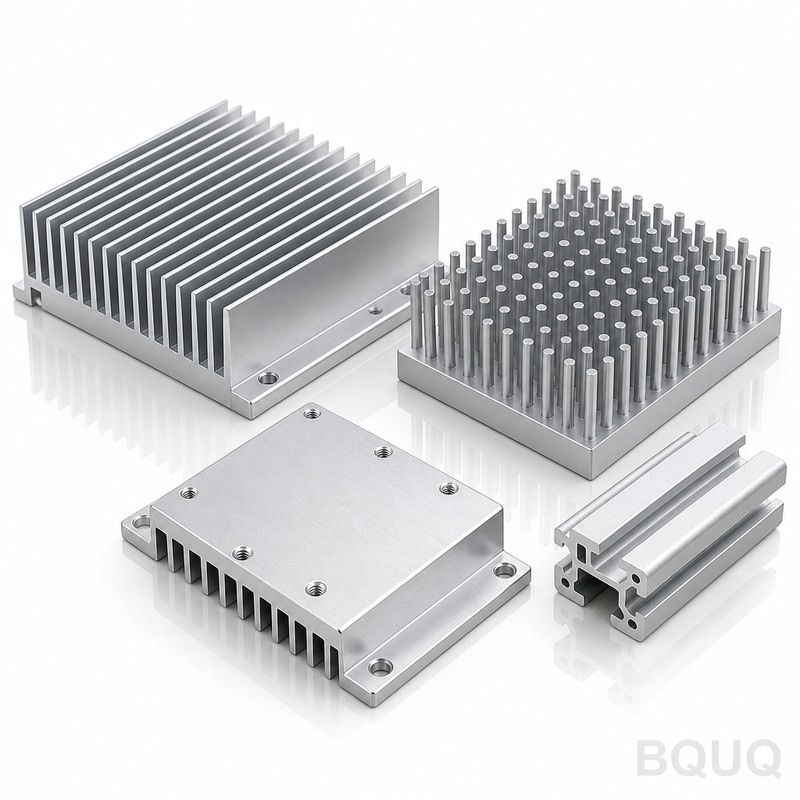
To calculate the total thermal resistance from the semiconductor junction to ambient, you add the three resistances in series: Rth(total) = Rth(j-c) + Rth(c-s) + Rth(s-a). For a typical TO-247 package, Rth(j-c) is about 0.24°C/W, a thermal pad with 0.5 mm thickness and 20 mm² area offers Rth(c-s) around 0.35°C/W, and a medium-sized extruded heat sink with 300 LFM airflow provides Rth(s-a) of 0.45°C/W. The total resistance is 1.04°C/W, meaning if the component dissipates 50 W, the junction rises 52°C above ambient. If your ambient is 50°C and the maximum junction temperature is 150°C, you have a margin of 48°C, so this design works; if the ambient were 70°C, you would need a larger heat sink or higher airflow.
What Are the Typical Rth Values for Different Heat Sink Types?
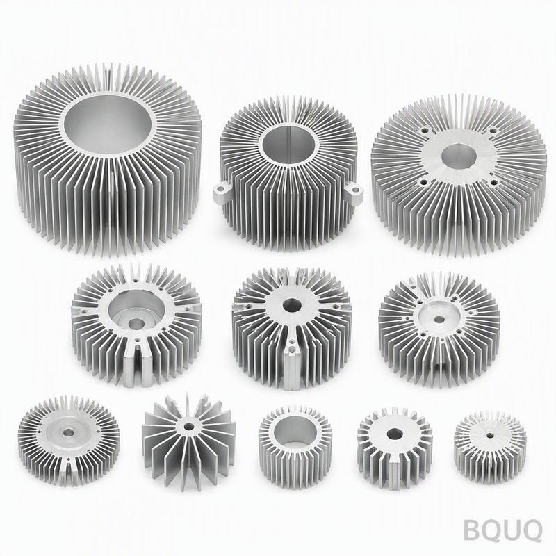
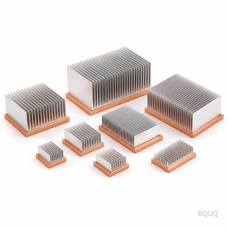
The Rth value varies dramatically with heat sink construction, and the table below shows real measured values for common types at a 75°C base-to-ambient temperature rise with natural convection unless noted. Extruded aluminum heat sinks with a flat base and straight fins are the most common, but their Rth depends heavily on the fin surface area and the thermal conductivity of the alloy (typically 180 W/m·K for 6063-T5 aluminum). Bonded fin heat sinks, where fins are epoxied or soldered into a base, offer lower Rth because they allow higher fin density, but they cost 20-40% more than extrusions. For high-power applications, copper heat sinks or copper-base aluminum-fin hybrids can reduce Rth by 30% compared to all-aluminum versions due to copper's thermal conductivity of 401 W/m·K.
| Heat Sink Type | Typical Rth(s-a) (°C/W) | Max Power Density (W/cm²) | Relative Cost per Unit |
| Extruded Aluminum, 50x50x25 mm | 2.50 (natural) / 0.85 (200 LFM) | 1.5 | 1.0x |
| Extruded Aluminum, 100x100x40 mm | 0.90 (natural) / 0.35 (300 LFM) | 3.0 | 2.3x |
| Bonded Fin, 100x100x50 mm | 0.45 (natural) / 0.18 (400 LFM) | 5.5 | 3.5x |
| Copper Base + Aluminum Fins, 100x100x40 mm | 0.70 (natural) / 0.28 (300 LFM) | 4.0 | 4.8x |
| Skived Fin, 100x100x50 mm | 0.38 (natural) / 0.15 (400 LFM) | 6.0 | 6.5x |
| Stamped Aluminum, 75x50x15 mm | 4.50 (natural) / 1.80 (200 LFM) | 0.8 | 0.6x |
Why Does Airflow Velocity Have Such a Strong Effect on Rth?
Airflow velocity is the dominant factor in forced convection cooling because it directly controls the convective heat transfer coefficient (h), which increases roughly with the square root of velocity. For a typical extruded heat sink, increasing airflow from 0 to 200 LFM (linear feet per minute) can reduce Rth(s-a) by 60%, and going from 200 to 500 LFM can further reduce it by another 40%. For example, a 100x100x40 mm heat sink with a natural convection Rth of 0.90°C/W drops to 0.35°C/W at 300 LFM and to 0.22°C/W at 600 LFM, but the pressure drop also increases from 0.02 inH₂O to 0.25 inH₂O, requiring a stronger fan. The practical limit is that beyond 800 LFM, the thermal improvement is marginal while the acoustic noise and fan power consumption rise exponentially, so most enclosure designs target 200-500 LFM.
Which Heat Sink Material Offers the Best Thermal Resistance per Dollar?
Aluminum 6063-T5 offers the best thermal resistance per dollar because it costs approximately $3.50 per kilogram, has a thermal conductivity of 180 W/m·K, and is easily extruded into complex fin geometries, whereas copper costs $12 per kilogram with 401 W/m·K but is heavier and requires machining or brazing. In a cost-performance comparison, an all-aluminum heat sink with a Rth of 0.90°C/W costs roughly $8.50 in production volumes of 1000 units, while a copper-base hybrid achieving 0.70°C/W costs $18.00, meaning you pay 2.1x more for a 22% improvement. For most applications below 200 W, aluminum is the rational choice; above 300 W, consider a copper base or heat pipe assembly because the size of an aluminum-only solution becomes impractical. Additionally, the weight penalty of copper is significant, since copper is 3.3x denser than aluminum, which may require additional mounting support in vibration-prone environments.
How Does Thermal Interface Material (TIM) Affect the Overall Rth?
The thermal interface material (TIM) between the component and the heat sink base adds a measurable resistance that can account for 10-30% of the total thermal path if not selected properly. A typical thermal grease with a thermal conductivity of 3.0 W/m·K and a bond line thickness of 50 microns yields an Rth(c-s) of approximately 0.20°C/W for a 25 mm² package, while a 0.5 mm thick silicone pad with 1.5 W/m·K gives 1.30°C/W for the same area. Using a phase-change material or a graphite pad with 10-15 W/m·K can reduce Rth(c-s) to 0.05-0.10°C/W, but these materials cost 5-8x more than silicone pads. The engineering rule is to use the thinnest TIM layer possible with the highest thermal conductivity, and always apply adequate mounting pressure (typically 20-50 psi for greases, 100-150 psi for pads) to minimize contact resistance.
What Measurement Errors Should You Avoid When Testing Rth?
The most common Rth measurement errors come from incorrect thermocouple placement, using an uncalibrated heat source, and ignoring heat losses through the leads or mounting hardware. Place the thermocouple at the center of the heat sink base directly under the heat source, not on the fin edge, because the temperature gradient across the base can be 5-10°C for a 100 mm wide sink. Use a calibrated power resistor or a dummy die with a known thermal resistance, and account for the 10-15% of heat that escapes through the PCB and leads by measuring the total electrical input power and subtracting known losses. Also, maintain a stable ambient temperature within ±1°C and allow at least 30 minutes for thermal equilibrium before recording the final temperature, since the time constant of a large heat sink can be 10-15 minutes.
When Should You Choose a Custom Heat Sink Instead of a Standard Extrusion?
Choose a custom heat sink when your standard extrusion cannot meet the Rth target within the available envelope, when your volume exceeds 5000 pieces per year, or when you need specific mounting holes, standoffs, or a specialized fin pattern for airflow direction. Custom extruded aluminum dies cost between $1,500 and $5,000 with a lead time of 4-6 weeks, and the per-unit cost drops by 30-40% compared to off-the-shelf parts when your quantity is above 2000 units. For volumes below 500 pieces, stick with standard extrusions and add a stamped or CNC-machined mounting plate, because the tooling amortization will not be justified. BQUQ can also provide bonded fin or skived fin custom designs with lead times of 2-3 weeks for prototypes and 4-5 weeks for production, including full CMM inspection reports for flatness (within 0.05 mm) and surface roughness (Ra 1.6 µm) on the base.
Can You Reduce Rth by Increasing the Heat Sink Surface Area Alone?
Yes, increasing the surface area reduces Rth, but with diminishing returns because the fin efficiency drops below 90% when fin height exceeds 25 mm or fin spacing is less than 3 mm in natural convection. For an extruded heat sink with 10 mm fins, increasing fin height from 20 mm to 40 mm reduces Rth by about 25%, but increasing from 40 mm to 60 mm only reduces it by another 10% because the fin tips are nearly at ambient temperature. The optimal fin spacing for natural convection is 6-10 mm, while forced convection allows spacing of 2-4 mm at 300 LFM, and going below 2 mm creates boundary layer interference that actually increases Rth. Always calculate the total wetted surface area and the fin efficiency factor (η_fin) using the formula η = tanh(mL) / (mL), where m is a function of thermal conductivity, heat transfer coefficient, and fin thickness.
How Does Orientation Affect the Rth of a Heat Sink in Natural Convection?
In natural convection, the heat sink orientation can change the Rth by 15-30% because buoyancy-driven airflow is strongly affected by the direction of the fin channels. Vertical orientation with fins aligned vertically provides the lowest Rth, typically 0.90°C/W for a 100x100x40 mm sink, while horizontal orientation with fins pointing upward increases Rth to approximately 1.10°C/W, and fins pointing downward (inverted) increases it to 1.35°C/W. The reason is that warm air rises through the vertical channels, creating a chimney effect that enhances airflow, whereas downward-facing fins trap the hot air under the sink. If your enclosure forces a horizontal orientation, increase the fin spacing by at least 2 mm or add a low-profile fan to compensate for the 20-30% performance loss.
FAQ
What Is a Good Rth Value for a Heat Sink?
A good Rth(s-a) value depends on your power dissipation and allowable temperature rise, but for most electronics, 0.5°C/W to 1.5°C/W is typical for 20-100 W loads in forced convection. For natural convection, expect 1.5°C/W to 4.0°C/W for the same size sink. If you need below 0.2°C/W, you will likely need liquid cooling or heat pipe assemblies.
How Do I Convert Rth from °C/W to K/W?
The conversion is a direct numerical equivalence because 1°C of temperature difference equals 1 Kelvin, so a Rth of 0.5°C/W is exactly 0.5 K/W. The units are interchangeable in engineering calculations, but K/W is preferred in scientific literature. Always use the same unit throughout your thermal analysis to avoid arithmetic errors.
Does a Larger Heat Sink Always Have a Lower Rth?
Larger heat sinks generally have lower Rth, but only if the added surface area is effective, meaning fins are properly sized and spaced for the airflow. Doubling the volume of a heat sink typically reduces Rth by 30-40%, not 50%, due to fin efficiency losses. Beyond a certain size, the weight and cost increase are not justified by the marginal thermal improvement.
What Is the Difference Between Rth(j-c) and Rth(s-a)?
Rth(j-c) is the thermal resistance from the semiconductor junction to the external case or package surface, and it is fixed by the component design, typically 0.1 to 1.0°C/W depending on package type. Rth(s-a) is the resistance from the heat sink base to the ambient air, which you can control through heat sink selection, airflow, and TIM quality. The sum of both, plus Rth(c-s), gives the total junction-to-ambient resistance.
How Often Should I Retest Rth in Production?
Retest Rth on a sample basis of 1-5 pieces per batch, especially if your heat sink is anodized, because the anodizing thickness (10-25 microns) adds a small insulation layer that increases Rth by 1-3%. Also verify the flatness of the base after machining because warpage of more than 0.1 mm can increase contact resistance by 5-10%. For high-reliability applications such as automotive or aerospace, perform a 100% visual inspection and a thermal test on every 100th unit.
Conclusion
Thermal resistance is not just a datasheet number; it is the governing parameter that determines whether your semiconductor survives its thermal environment, and a proper Rth calculation will save you from costly field failures. Always measure your actual Rth under your specific airflow and mounting conditions, because datasheet values are typically measured with ideal flat surfaces and clean air. If you are designing a high-power system and need a custom heat sink with a guaranteed Rth, BQUQ provides free thermal simulation and prototyping services. Send us your CAD file or power dissipation requirements for a 12-hour quote with DFM feedback, and we will deliver production-ready heat sinks with full Rth test reports. Contact us at sc@bquq.com, WhatsApp +86 13713157787, or visit www.bquq.com.
Related Articles
- Best Copper Heat Sinks for CPU Overclocking in 2025
- Stamped Metal vs Die Cast Heat Sinks: Cost & Quality Comparison
- New energy vehicle IGBT heat dissipation, heat sink reliability engineering, heat pipe and temperature plate integrated heat sink, surface treatment and heat radiation enhancement: anodic oxidation, black coating and micro-nano structure, graphene/3D printing/intelligent thermal management: 2030 heat sink technology roadmap


