
What Is Thermal Resistance in Heat Sinks? Rth Explained for Designers
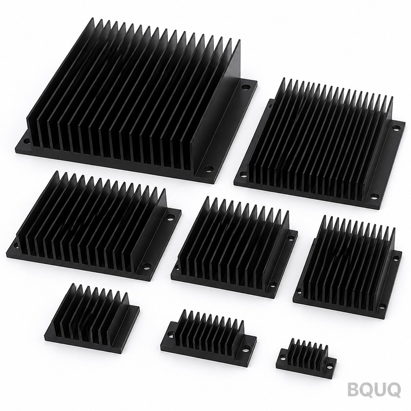
Thermal resistance (Rth) is the quantitative measure of a heat sink's opposition to heat flow, expressed in degrees Celsius per watt (°C/W). It directly defines the temperature rise between the heat source and the ambient air for every watt of power dissipated, enabling you to predict junction temperatures with a simple equation. For a typical extruded aluminum heat sink, Rth values range from 0.1°C/W for large forced-air units to over 5°C/W for small natural convection models.
How Do You Calculate the Required Thermal Resistance for Your Application?
The core design equation is TJ = TA + (P × Rth_total), where TJ is the maximum allowable junction temperature, TA is the ambient air temperature, and P is the heat load in watts. To solve for the maximum acceptable heat sink thermal resistance, use Rth_sink = (TJ_max - TA) / P - Rth_junction - Rth_interface. For example, if your IGBT has a junction-to-case Rth of 0.25°C/W, you apply a 0.1°C/W thermal pad, dissipate 50W, and need TJ below 125°C in a 40°C ambient, the heat sink must provide no more than (125 - 40)/50 - 0.25 - 0.1 = 1.35°C/W. This calculation is the first step in any heat sink selection, and BQUQ engineers use it daily to match extrusions and bonded fin assemblies to specific power electronics.
What Is the Difference Between Rth Junction-to-Case, Case-to-Sink, and Sink-to-Ambient?
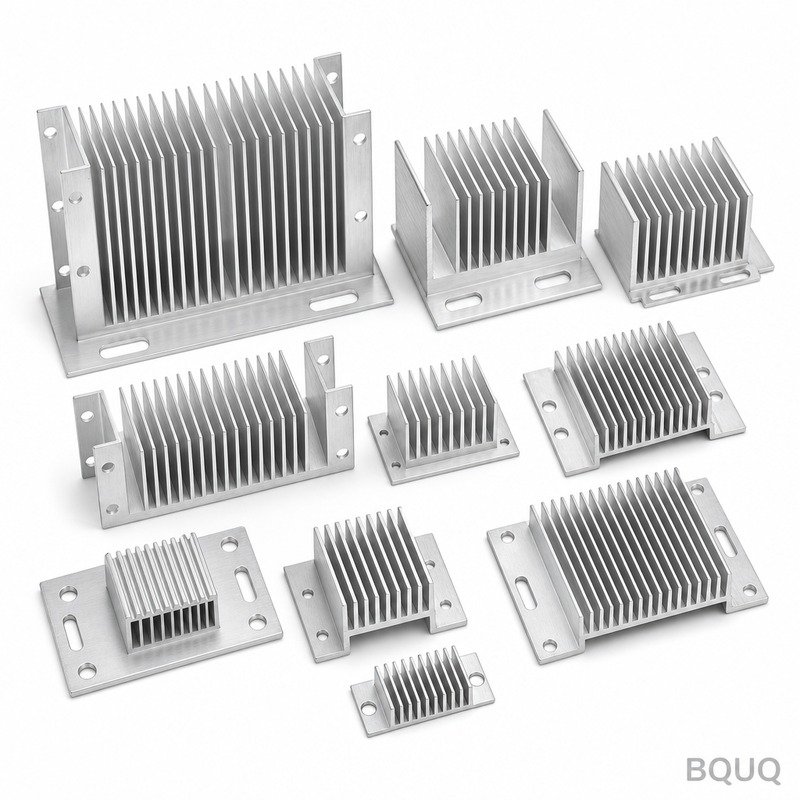
The total thermal resistance path has three distinct components, each with its own material and geometry. Rth(junction-to-case) is the internal resistance of the semiconductor package, typically 0.1 to 1.0°C/W for MOSFETs and IGBTs, and it is fixed by the component manufacturer. Rth(case-to-sink) is the interface resistance, which can be as low as 0.02°C/W with high-performance thermal grease and proper mounting pressure, but rises to 0.5°C/W or more with a dry mica insulator or poor surface flatness. Rth(sink-to-ambient) is the heat sink's own resistance, which depends on fin area, airflow, and material, and is the only component you can freely adjust during design.
Which Factors Most Strongly Influence a Heat Sink's Thermal Resistance Value?
Airflow velocity is the dominant factor, with a single fan increasing heat sink performance by 5 to 10 times compared to natural convection. At natural convection (0 m/s), a typical extruded heat sink with 100mm width and 50mm fin height might have Rth of 0.8°C/W, but at 3 m/s forced airflow, the same sink drops to 0.15°C/W. Surface area and fin density are second, where increasing fin count from 8 to 14 fins per inch on a 200mm long sink improves Rth by roughly 40%, but beyond 16 fins per inch natural convection performance degrades due to restricted air flow. Material choice matters less: aluminum 6063-T5 has a thermal conductivity of 180 W/m·K, while copper offers 390 W/m·K, but because copper is 3.3 times heavier and significantly more expensive, aluminum extrusions remain the industry standard for 95% of applications.
How Does Heat Sink Orientation Affect the Rth Value in Natural Convection?
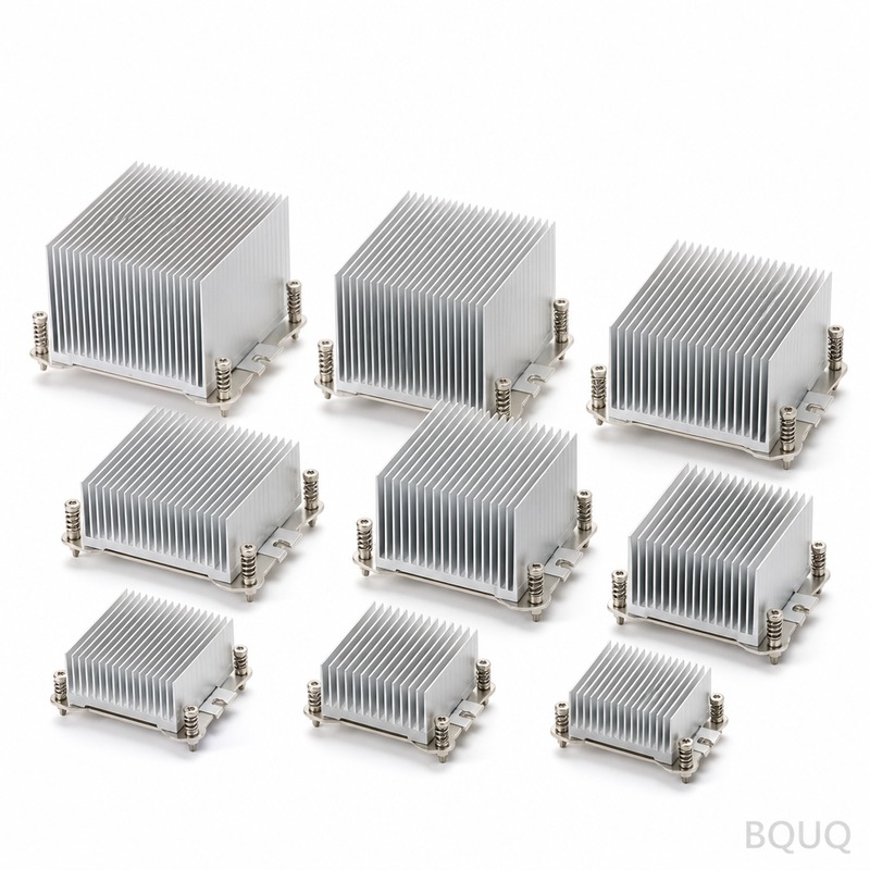
Orientation changes the natural convection airflow pattern and can shift Rth by 15% to 30%. When the heat sink fins are vertical and the base is vertical, air rises freely through the fin channels, giving the lowest Rth; when the base is horizontal and fins point upward, performance drops by about 10% due to reduced chimney effect. The worst orientation is fins pointing downward, which traps hot air under the base and can increase Rth by 20-35% compared to the best vertical orientation. For LED lighting fixtures and outdoor enclosures where orientation is fixed, BQUQ recommends testing the actual mounted position because datasheet Rth values typically assume ideal vertical fin orientation.
What Are Typical Rth Values and Price Ranges for Standard Heat Sink Types?
The table below shows representative Rth values and cost figures for common heat sink formats manufactured at BQUQ, based on a 100mm × 100mm base area and a 40°C ambient temperature.
| Heat Sink Type | Rth at 0 m/s (°C/W) | Rth at 3 m/s (°C/W) | Weight (g) | Unit Price (USD, QTY 1000) |
| Extruded aluminum, low profile (25mm fin) | 1.8 | 0.45 | 280 | 2.10 |
| Extruded aluminum, high fin (50mm fin) | 0.9 | 0.22 | 520 | 3.80 |
| Bonded fin aluminum (80mm fin, 20 fins) | 0.5 | 0.12 | 780 | 6.50 |
| Skived copper (40mm fin) | 0.6 | 0.10 | 1100 | 12.40 |
| Forged aluminum pin fin (30mm pin) | 1.2 | 0.28 | 340 | 4.90 |
| Stamped aluminum, folded fin (50mm) | 1.5 | 0.38 | 210 | 1.60 |
These values assume a polished base with flatness of 0.05mm and a 0.1mm thermal grease interface. For a 100W heat load at 3 m/s, the bonded fin sink would produce a sink-to-ambient temperature rise of only 12°C, while the stamped sink would rise 38°C, a critical difference for junction temperature margin.
How Can You Reduce the Rth Value Through Surface Treatment and Interface Materials?
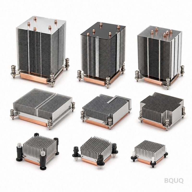
The base-to-sink interface is often where designers lose the most thermal performance. Applying a 0.025mm layer of silver-filled thermal grease with a thermal conductivity of 3.5 W/m·K reduces Rth(case-to-sink) by 60% compared to a dry joint, while a 0.5mm silicone pad with 1.5 W/m·K adds about 0.3°C/W of resistance. Anodizing the heat sink surface to a thickness of 20 microns improves the emissivity from 0.04 (bare aluminum) to 0.85, which increases radiation heat transfer by 15-20% in natural convection but has negligible effect under forced airflow. For high-power IGBT modules, BQUQ recommends a flatness of 0.03mm on the mounting surface and a mounting torque of 0.6 N·m per screw, which ensures the thermal grease layer stays below 0.05mm thick.
Why Does the Rth Value Change with Heat Load and Temperature?
Thermal resistance is not perfectly constant; it varies with temperature and power level because material conductivity and convection coefficients change. Aluminum's thermal conductivity decreases by about 5% from 20°C to 150°C, while air viscosity increases with temperature, reducing convection efficiency and raising Rth(sink-to-ambient) by 8-12% at a 100°C temperature rise. Natural convection Rth also degrades at high heat loads because the boundary layer becomes turbulent and less effective, whereas forced convection remains more stable. When using datasheet Rth values, apply a correction factor of 1.1 to 1.2 for hot environments above 70°C, and always design with a 15% safety margin on the calculated Rth to account for dust accumulation and aging of thermal interface materials.
What Common Mistakes Cause Actual Rth to Be Higher Than Datasheet Values?
The most frequent error is ignoring the interface resistance, assuming the heat sink Rth alone determines junction temperature. A typical TO-247 package without thermal compound can have a case-to-sink Rth of 1.0°C/W, which is often larger than the heat sink itself. The second mistake is underestimating the effect of component placement: mounting a 50W device at the edge of the heat sink instead of the center increases effective Rth by 20-25% because heat spreads unevenly across the base. Third, many designers forget that the datasheet Rth often assumes a 75mm fan blowing directly at the center, but real enclosures have restricted airflow and recirculation, so a derating of 30% is wise. BQUQ's engineering team offers free thermal simulation for customers who provide their device specs and mounting layout, helping avoid these costly errors before tooling.
Can You Lower Rth by Changing the Heat Sink Material from Aluminum to Copper?
Yes, copper reduces Rth by approximately 30-40% compared to aluminum for the same geometry, but the cost and weight penalties are substantial. A copper heat sink costs 4 to 6 times more than an equivalent aluminum extrusion and weighs 3.3 times as much, which often creates mechanical stress issues in vibration environments. The best compromise is a copper base plate (3-6mm thick) bonded to aluminum fins, which improves heat spreading by 40% at the base while keeping weight and cost increases under 50%. For applications where every degree matters, such as high-power laser diodes or RF amplifiers, BQUQ manufactures copper-skived heat sinks with Rth as low as 0.05°C/W at 5 m/s airflow.
FAQ Section
What Is a Good Rth Value for a CPU Heat Sink?
A good CPU heat sink for a 125W processor should have an Rth(sink-to-ambient) between 0.15 and 0.3°C/W under a 120mm fan at 1500 RPM. High-end tower coolers achieve about 0.1°C/W, while stock aluminum coolers are typically 0.4 to 0.6°C/W. Always verify this value against your processor's TDP and maximum junction temperature.
How Do I Measure the Rth of a Custom Heat Sink?
Mount a calibrated power resistor or heating element to the heat sink base with thermal grease, apply a known power (e.g., 50W), and measure the base temperature with a thermocouple after reaching steady state (usually 30-45 minutes). Subtract the ambient temperature and divide by the power to get Rth in °C/W. Repeat at different power levels to confirm linearity, and use at least three thermocouples for accuracy.
Does a Larger Heat Sink Always Have a Lower Rth?
Yes, up to a point, because increasing fin length and base area directly increases convective surface area. However, beyond a certain size, the marginal improvement diminishes; doubling the volume of an aluminum heat sink typically reduces Rth by only 30-40% because the added area is less effective. For extreme heat loads above 500W, multiple heat sinks or liquid cooling become more cost-effective than oversized air-cooled units.
How Often Should Thermal Grease Be Replaced to Maintain Rth?
For industrial applications with continuous operation at high temperature, replace thermal grease every 2 to 3 years because pump-out and dry-out degrade the interface Rth by 20-30%. In clean, temperature-cycled environments, check the interface annually and inspect for cracking or separation. Phase-change materials last longer, often 5 years, and are preferred for automotive and outdoor equipment.
What Is the Difference Between Rth and Thermal Impedance?
Rth is a steady-state value measured in °C/W, while thermal impedance (Zth) includes transient behavior and is expressed in °C·s/W. Zth is important for pulsed loads where the heat sink does not reach steady state, such as motor drives with short overloads. For a 10-second pulse, Zth can be 30-50% lower than Rth because the heat sink mass absorbs energy without fully raising the junction temperature.
Can I Use Multiple Heat Sinks in Parallel to Reduce Rth?
Yes, mounting two identical heat sinks on the same device in parallel halves the effective Rth, provided the base has a thick copper or aluminum spreader plate. The combined Rth is approximately half of a single sink, but only if the thermal interface and mounting pressure are identical on both. This approach is common in high-power audio amplifiers and industrial inverters where space permits.
What Is the Maximum Operating Temperature for an Aluminum Heat Sink?
Aluminum 6063-T5 maintains its mechanical strength up to 200°C, but the thermal performance degrades above 150°C due to increased radiation and convection losses. The practical limit for a structural heat sink is 120-150°C, beyond which thermal expansion may cause the base to warp and break the interface bond. For continuous operation above 150°C, use copper or a ceramic-coated aluminum heat sink.
Conclusion
Understanding and calculating Rth is the single most important step in thermal design, because it converts a vague requirement of "keep it cool" into a precise engineering specification. You now have the equations, typical values, and real-world correction factors to select or custom-design a heat sink with confidence. If you need a heat sink with a specific Rth target, BQUQ's 20-year experience in CNC machining, extrusion, and stamping ensures we can manufacture it with tolerances as tight as ±0.05mm. Send your thermal requirements to sc@bquq.com or WhatsApp +86 13713157787, and our engineers will provide a thermal simulation and quotation within 12 hours. Visit www.bquq.com for our full heat sink catalog and design guides.


