
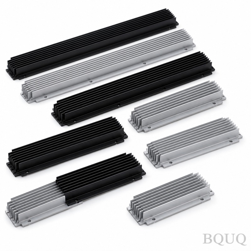
Why Do Heat Sinks Have Fins? Fin Spacing Explained
The primary reason heat sinks have fins is to exponentially increase the surface area available for convective heat transfer, allowing heat to dissipate from a hot component into the surrounding air more efficiently. Fins transform a flat, low-surface-area base into a high-aspect-ratio structure that maximizes airflow contact, which is governed by Newton's Law of Cooling. The spacing between these fins is a critical engineering compromise: too tight and airflow is choked, too wide and surface area is wasted.
What Is the Physics Behind Fin Efficiency and Airflow?
Fins work by conducting heat from the base plate into the thin metal protrusions, then releasing that heat into the air via convection. The efficiency of this process depends on the fin's material (typically aluminum 6063-T5 with a thermal conductivity of 200 W/m·K) and its geometry. According to Newton's Law of Cooling, the heat dissipated (Q) equals the heat transfer coefficient (h) multiplied by the surface area (A) multiplied by the temperature difference (ΔT). Since the heat transfer coefficient for natural air convection is low (5-25 W/m²·K), engineers rely on increasing the surface area (A) by factors of 10 to 20 times to achieve adequate cooling. For a typical 100W processor, a bare base plate would need to be over 1 square meter to stay below 85°C, whereas a finned heat sink of 100mm x 100mm can achieve the same result.
How Does Fin Spacing Affect Thermal Performance?
Fin spacing directly controls the boundary layer thickness and airflow velocity. When fins are too close together (below 2mm pitch), the boundary layers of adjacent fins overlap, creating stagnant air pockets that act as insulators. When spacing is too large (above 10mm pitch), the surface area per unit volume drops, and the heat sink becomes ineffective and bulky. The optimal spacing for natural convection is typically between 4mm and 7mm pitch, which allows the buoyant hot air to rise freely without resistance. For forced convection (with fans), spacing can be reduced to 1.5mm to 3mm pitch because the fan provides sufficient pressure to overcome the viscous drag.
Which Factors Determine the Ideal Fin Pitch for Your Application?
The ideal fin pitch is determined by four primary variables: airflow mode (natural vs. forced), ambient temperature, heat load (watts), and allowable height. In natural convection applications (no fan), the fin pitch must be wide enough to permit free air rising; a standard rule of thumb is a fin gap of 6mm to 8mm with a fin height of 20mm to 40mm. In forced convection, a fan with a static pressure of 2-5 mmH₂O can push air through 2mm gaps effectively. Additionally, the orientation of the heat sink (horizontal vs. vertical) matters; vertical fins with 6mm spacing show a 15-20% improvement in natural convection compared to horizontal fins due to the chimney effect.
What Are the Standard Fin Spacing Values and Their Trade-offs?
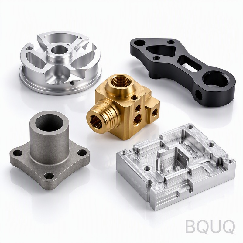
Manufacturers like BQUQ (with 20 years in heat sink production) typically offer standard fin spacing ranges that balance manufacturability and performance. For skived or extruded heat sinks, the minimum fin thickness is 1.0mm with a minimum gap of 1.5mm. For stamped fin assemblies, the pitch is often 3mm to 5mm because the tooling limits the fin thickness to 0.3mm to 0.6mm. The table below shows typical values for common applications:
| Application | Airflow Mode | Fin Pitch (mm) | Fin Thickness (mm) | Height (mm) | Typical Performance (K/W) |
| LED Street Light | Natural | 6.5 | 2.0 | 25 | 0.85 |
| CPU Cooler | Forced (fan) | 2.5 | 0.4 | 35 | 0.12 |
| IGBT Module | Forced (high static) | 3.0 | 1.2 | 40 | 0.08 |
| Passive Power Supply | Natural | 7.0 | 2.5 | 30 | 1.20 |
| GPU Heatsink | Forced (blower) | 2.0 | 0.3 | 25 | 0.15 |
| Telecom Base Station | Natural | 8.0 | 3.0 | 45 | 0.65 |
How Does Fin Spacing Impact Manufacturing Cost and Tooling?
Fin spacing significantly affects the manufacturing method and cost. For CNC machining, a fin pitch below 2.0mm requires a 1.0mm end mill, which increases machining time by 40% and tool wear by 60% compared to a 3.0mm pitch. For extrusion, a pitch below 2.5mm makes the aluminum die fragile, reducing die life from 50,000 kg of extrusion to only 15,000 kg. For stamping, the fin pitch is dictated by the die design; a 3.0mm pitch allows a standard progressive die (costing $8,000-$15,000) while a 1.5mm pitch requires a complex die with tighter tolerances (costing $20,000-$30,000). Therefore, engineers should always specify the widest fin pitch that meets the thermal budget to minimize unit cost.
When Should You Choose Dense Fins Versus Sparse Fins?
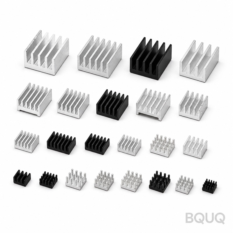
Dense fins (pitch < 3mm) are only recommended when you have a dedicated fan with high static pressure (above 3 mmH₂O) and the heat load exceeds 150W per 100mm². Sparse fins (pitch > 6mm) are optimal for passive cooling, outdoor enclosures, and applications with dust accumulation because wider gaps are less prone to clogging. A practical example: a 300W IGBT heatsink with 2.5mm pitch and a 120mm fan achieves a thermal resistance of 0.05 K/W, while the same heatsink without a fan would require a 9mm pitch and be 3 times larger to achieve the same resistance. Dust is a critical factor; in environments with particulate matter, a 4mm fin gap is the minimum recommended to avoid performance degradation over time.
How Do You Calculate the Optimal Fin Spacing for a Custom Design?
For a quick engineering estimate, use the correlation for natural convection: optimal fin gap (mm) equals 1.5 multiplied by the cube root of the fin height (mm). For a 30mm fin height, this gives a gap of 4.6mm. For forced convection, the optimal gap can be calculated using the hydraulic diameter approach, but a simpler rule is to set the gap to 1.5 to 2.0 times the fan's boundary layer thickness, which is typically 1.5mm to 2.5mm. BQUQ recommends running a computational fluid dynamics (CFD) simulation for any fin pitch below 2.0mm, as the manufacturing tolerance of ±0.1mm can cause a 5% variation in thermal performance. Always specify the fin pitch tolerance in your drawing; a standard tolerance is ±0.15mm for extruded profiles and ±0.05mm for CNC machined fins.
What Are the Common Mistakes in Fin Spacing Design?
The most common mistake is specifying a fin pitch that is too small for the available airflow, leading to a heat sink that performs worse than a flat plate. The second mistake is ignoring the fin efficiency; if the fins are too tall (above 50mm) with a thickness below 1.0mm, the fin tips become ineffective because the temperature drops significantly along the fin height. For aluminum, a fin thickness of 1.5mm to 2.0mm ensures over 90% fin efficiency for heights up to 40mm. The third mistake is failing to account for the heat sink's orientation; a heat sink designed for vertical airflow will lose 30% of its capacity if mounted horizontally. Finally, many engineers forget to include the thermal interface material (TIM) resistance in their calculations, which adds 0.1 to 0.5 K/W depending on the material and mounting pressure.
Conclusion
Fin spacing is not a cosmetic choice but a thermodynamic optimization that balances surface area, airflow resistance, and manufacturing cost. For natural convection, use a pitch of 6mm to 8mm; for forced convection, use a pitch of 2mm to 3mm, and always verify with thermal simulation or prototype testing. By understanding the relationship between fin geometry and heat transfer, you can reduce your heat sink size by up to 40% while maintaining the same thermal performance.
How Quickly Can BQUQ Provide Fin Spacing Design Assistance?
BQUQ offers rapid prototyping for heat sinks with custom fin spacing, and our engineering team can provide thermal simulation results within 24 hours. We manufacture using CNC machining, stamping, and extrusion, allowing us to produce fin pitches from 1.2mm to 10mm with tolerances as tight as ±0.05mm.
What Is the Minimum Fin Pitch BQUQ Can Manufacture?
Our CNC machining department can achieve a minimum fin pitch of 1.2mm with a fin thickness of 0.8mm, while our stamping process can achieve a pitch of 2.0mm with a thickness of 0.3mm. For extrusion, the minimum pitch is 2.5mm due to die strength limitations. These capabilities allow us to serve applications from passive LED cooling to high-performance microprocessor heat sinks.
How Does Fin Spacing Affect the Price of a Custom Heat Sink?
Fin spacing directly impacts the cost per unit; a heat sink with 2.0mm pitch will cost roughly 25% more than an equivalent unit with 4.0mm pitch due to increased machining time and tool wear. For volumes above 5,000 pieces, stamping with a pitch of 3.0mm offers the lowest cost at approximately $1.50 to $3.00 per unit, while CNC machined prototypes with 2.0mm pitch start at $50 per unit.
What Is the Typical Lead Time for a Custom Heat Sink with Specific Fin Spacing?
For an extruded heat sink with custom fin spacing, the die fabrication takes 2 to 3 weeks, and production runs take an additional 1 to 2 weeks. CNC machined heat sinks with custom fin spacing can be delivered in 3 to 5 days for prototypes. Stamped heat sinks require 4 to 6 weeks for tooling and first articles.
Can Fin Spacing Be Optimized for Both Natural and Forced Convection?
Yes, but a hybrid design is required, typically using a variable pitch where the fins are wider at the base and narrower near the top. Alternatively, you can use a dual-mode design with a fan that can be switched off; in this case, a pitch of 4.5mm to 5.0mm offers the best compromise, providing 80% of the natural convection performance of a 7mm pitch and 90% of the forced convection performance of a 2.5mm pitch.
How Do I Submit a Heat Sink Design for a Quotation?
You can send your 3D model (STEP or IGES format) and thermal requirements (watts, ambient temperature, max case temperature) to sc@bquq.com. Our engineers will review the fin spacing, simulate the thermal performance, and provide a quotation with DFM (Design for Manufacturing) feedback within 12 hours. For urgent inquiries, contact us via WhatsApp at +86 13713157787 or visit our website at www.bquq.com.
Related Articles
- Best Copper Heat Sinks for CPU Overclocking in 2025
- New energy vehicle IGBT heat dissipation, heat sink reliability engineering, heat pipe and temperature plate integrated heat sink, surface treatment and heat radiation enhancement: anodic oxidation, black coating and micro-nano structure, graphene/3D printing/intelligent thermal management: 2030 heat sink technology roadmap
- Hardware heat sink reconstruction under liquid-cooled penetration of AI server: cold plate, microchannel and two-phase flow


