
CPU Cooler Design: Tower, Low-Profile and AIO
Short answer: Pick the CPU cooler by three numbers first: sustained TDP, available height, and airflow path. A tower air cooler with 4–6 heat pipes typically handles 120–220 W at 150–160 mm tall; a low-profile cooler fits under 40–70 mm but usually caps out near 65–100 W; a 240–360 mm AIO moves 200–350 W with the radiator mounted elsewhere. Cost tracks copper mass and fin area, not brand. For custom or OEM builds, BQUQ machines and stamps heat sink components in one ISO9001 Dongguan factory to ±0.005 mm on CNC features, with quotes returned in 12 working hours.
How does a CPU cooler actually move heat?
Every CPU cooler is a chain of four resistances, and the weakest link sets the temperature. Heat leaves the die through the integrated heat spreader (IHS), crosses thermal interface material (TIM), spreads into a base plate, travels up heat pipes or through a cold plate, and finally leaves the fins into moving air.
That chain is why a bigger fan rarely fixes a hot CPU. If the base plate is small or the solder between pipe and fin is poor, extra airflow only cools fins that were never getting heat in the first place.
The practical model engineers use is a thermal resistance network: junction-to-case, case-to-sink, sink-to-air. Each stage adds °C per watt. A cooler rated "180 W" is simply one whose total resistance keeps a typical die under its throttle point at that load. Once you know the resistance budget, geometry choices become arithmetic instead of guesswork. Our breakdown of how a heat sink thermal resistance network is built walks through the math stage by stage.
Conduction, spreading, and convection
- Conduction depends on material and cross-section. Copper conducts at roughly 385 W/m·K, aluminum at about 200 W/m·K. Copper wins on paper, but it is roughly three times denser and more expensive.
- Spreading is the hidden cost. A 40 × 40 mm die dumping 150 W into a 60 mm base creates a hot spot. Thicker bases and vapor chambers exist purely to spread that flux sideways.
- Convection is fin area times airflow. Fin count, fin thickness, fin gap and static pressure all interact — dense fins need high static pressure or they starve.
Tower, low-profile or AIO: which architecture fits?
The three mainstream architectures are not better or worse in the abstract. They solve different constraints.
| Architecture | Typical height | Typical sustained TDP | Airflow requirement | Best-fit build |
|---|---|---|---|---|
| Tower air (4–6 heat pipes) | 150–165 mm | 120–220 W | One 120/140 mm PWM fan, 1–3 m/s face velocity | Standard ATX mid-tower, gaming, workstation |
| Low-profile (top-down) | 35–70 mm | 65–100 W | 80–92 mm fan, tight clearance | SFF, 1U/2U rack, industrial panel PC |
| AIO liquid (240/280/360 mm) | Pump 30–55 mm; radiator remote | 200–350 W | 2–3 fans on radiator, push or push-pull | High-TDP CPUs, RAM-clearance-limited builds |
| Passive / fanless | Varies, often 80–150 mm | 15–45 W | Case-level convection only | Fanless industrial, kiosk, embedded |
Two rules of thumb hold up in practice. First, height is usually the binding constraint, not TDP — measure from the IHS to the side panel before choosing anything. Second, low-profile coolers lose performance mostly because of fin area and recirculation, not because of a bad base. A top-down cooler pushes hot air back onto the motherboard, which is fine in a ducted industrial chassis and poor in a closed glass-panel case.
AIOs trade a fixed height problem for a mounting and pump-lifetime problem. They also add a second thermal interface (cold plate to coolant) and a pump that consumes 2–6 W and never fully stops making noise.
When does a vapor chamber beat heat pipes?
When the die is small and the wattage is high — think 200 W+ into a sub-50 mm² hotspot, or a low-profile cooler with almost no vertical room to run pipes. A vapor chamber spreads in two dimensions instead of one, which flattens the hot spot before heat reaches the fins. Below roughly 100 W in a normal tower, the extra cost rarely pays back.
What materials and manufacturing route should you specify?
This is where design intent meets the factory floor, and where cost is really decided.
| Component | Common material | Typical process | Notes |
|---|---|---|---|
| Base plate | Copper C1100 or aluminum 6063 | CNC milling, skiving, forging | Flatness and surface roughness drive TIM performance |
| Heat pipes | Copper tube, sintered powder wick | Purchased, then bonded | Grooved wick is cheaper, sintered handles orientation better |
| Fins | Aluminum 1050/6063, sometimes copper | Stamping, skiving, extrusion, folding | Fin gap 1.0–2.0 mm typical for 120 mm fans |
| Bonding | Solder paste, epoxy, thermal adhesive | Reflow or cure | Solder gives lower resistance; adhesive is cheaper and lighter |
| Mounting | Stainless or spring steel | Stamping, forming | Backplate stiffness prevents socket bow |
For tower and low-profile air coolers, the fin stack is usually the highest-volume part, and it sets unit cost. Stamped fins are cheapest at volume; skived fins give a continuous copper or aluminum base with no bond line, which is attractive when you need the lowest possible spreading resistance. How the skiving process turns a solid block into fins explains the trade-offs in tool wear, fin height limits and minimum fin gap.
For AIO cold plates, the microchannel geometry inside the plate matters more than anything visible from outside. Channel width, depth and wall thickness control both thermal resistance and pressure drop — and pressure drop decides how much pump you must pay for.
Copper versus aluminum: the honest split
Use copper where heat is dense and space is short: base plates, heat pipe walls, vapor chamber shells, and skived fin stacks in premium low-profile coolers. Use aluminum where heat is already spread: fin stacks in towers, brackets, shrouds, and extruded housings. A copper-base-aluminum-fin design captures most of the benefit at a fraction of the mass. Pure copper fin stacks exist, but they are heavy, expensive, and usually a marketing decision rather than an engineering one.
How do you size the fin stack and fan together?
Fin geometry and fan selection are one decision, not two.
- Fin gap. For a 120 mm fan at 1500–2000 RPM, 1.2–1.8 mm gaps are the sweet spot. Tighter than 1.0 mm raises static pressure demand sharply and clogs with dust faster.
- Fin thickness. 0.3–0.5 mm aluminum is typical for stamped fins. Thinner saves mass and cost but reduces conduction along the fin.
- Fin height and count. Total surface area is the goal; a taller stack with the same footprint adds area but also adds air-path resistance.
- Fan curve. Match the fan's pressure-flow curve to the stack's impedance. A high-CFM, low-pressure fan on a dense stack is a common and expensive mistake.
For industrial and rack applications, the same logic applies with different constraints — dust, vibration, 24/7 duty, and often a fixed 1U or 2U height. In those cases a ducted low-profile cooler with a high-static-pressure blower usually beats a larger open cooler that cannot get clean air.
If you are still at the concept stage, building one or two physical samples early is far cheaper than discovering a fin-gap problem after tooling. How to run a custom heat sink prototype build covers what to specify so the first sample is actually representative.
What does BQUQ manufacture for CPU cooler programs?
BQUQ runs four production lines in one Dongguan factory under ISO9001: CNC machining, metal stamping, custom springs, and heat sink production. For CPU cooler and electronics-cooling programs that means the base plate, fin stack, brackets and mounting hardware can all come from one supplier instead of four.
Capabilities relevant to cooler design:
- CNC machining to ±0.005 mm on base plates, cold plates, mounting blocks and vapor chamber shells, including flatness control on the TIM-facing surface.
- Metal stamping for fins, backplates, brackets, clips and shrouds, with progressive-die tooling for volume.
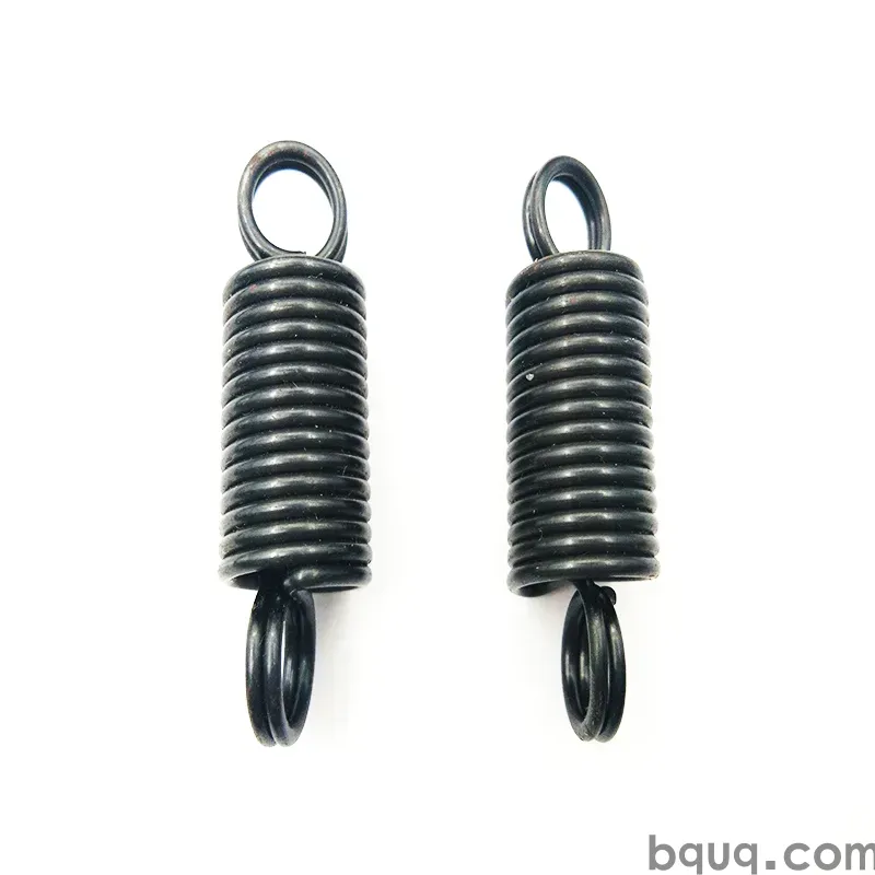
- Custom springs for mounting hardware — compression, torsion and helical forms that hold consistent socket pressure without over-bowing the board.
- Heat sink assembly across extruded, skived, stamped-fin, folded-fin and bonded-fin constructions, plus copper-base-aluminum-fin builds.
MOQ is flexible, so a 50-piece engineering run and a 50,000-piece production order go through the same process control. Quotes come back in 12 working hours.
What to send for a fast quote
1. A 3D model or 2D drawing with critical dimensions and tolerances.
2. Sustained and peak TDP, plus ambient temperature.
3. Height, footprint and mounting-hole constraints.
4. Fin material preference, if any, and whether bonding is soldered or adhesive.
5. Surface finish: bare aluminum, anodized, nickel-plated copper, or masked contact areas.
6. Annual volume and whether tooling amortization is acceptable.
With those six items, a manufacturable counter-proposal usually comes back the same day.
Frequently Asked Questions
Q: Is a tower air cooler or an AIO better for a 150 W CPU?
A: Both work. A 5–6 heat pipe tower at roughly 155 mm tall typically holds a 150 W load with a single 120 mm fan and no pump to fail. A 240 mm AIO handles the same load with lower peak temperatures but adds pump noise, a second interface and a finite service life. Choose by chassis clearance and noise target, not by headline wattage.
Q: How much height does a low-profile CPU cooler really need?
A: Plan on 40–70 mm from the IHS to the top of the fan for 65–100 W parts. Below 40 mm you are usually limited to 35–65 W unless you use a vapor chamber or a ducted blower. Always measure to the side panel, not to the motherboard, and allow 2–3 mm for socket and board tolerance.
Q: Does copper always beat aluminum in a CPU cooler?
A: No. Copper conducts roughly twice as well but is about three times denser and more costly. Copper pays off where heat is dense — base plates, heat pipe walls, vapor chambers, skived stacks. For the fin stack, aluminum bonded to a copper base gives most of the performance at a fraction of the weight and cost.
Q: What fin gap should I specify for a 120 mm fan?
A: For a 120 mm fan running 1500–2000 RPM, 1.2–1.8 mm gaps are typical and give a good balance of surface area and airflow. Going below 1.0 mm raises static pressure demand, increases noise and clogs faster with dust. Above 2.5 mm you lose surface area without a meaningful airflow gain.
Q: Can BQUQ supply both the heat sink and the mounting hardware?
A: Yes. One ISO9001 factory in Dongguan runs CNC machining, metal stamping, custom springs and heat sink production across four lines, so base plates, fins, backplates, clips and springs ship as one assembled kit. CNC features hold ±0.005 mm, MOQ is flexible, and quotes return in 12 working hours.
Related Resources
- About BQUQ and our four Dongguan production lines: /about/
- Heat sink products, including extruded and skived profiles: /heat-sinks/
- CNC machined heat sinks and cold plates: /cnc-machined-heat-sinks/
- Industry trends in thermal management: /industry-dynamics/
- Technical articles on heat sink design and manufacturing: /bquq-blog/
- Frequently asked questions on quoting and tolerances: /faq/
- Case studies from electronics and industrial programs: /case/
- Contact engineering for a 12-hour quote: /contact/
Authored by the BQUQ Engineering Team. BQUQ (Dongguan) runs CNC machining (±0.005 mm), metal stamping, custom springs, and heat sink production in one ISO9001 factory. Source-direct from Dongguan, China — quote in 12 hours: sc@bquq.com | WhatsApp +86 13713157787 | www.bquq.com


